Viking Pump TSM630.3: N-RS Universal Seal User Manual
Page 10
SECTION TSM 630.3
ISSUE
H
PAGE 10 OF 13
When installing carbon graphite bushings, extreme care must
be taken to prevent breaking. Carbon graphite is a brittle
material and easily cracked. If cracked, the bushing will
quickly disintegrate. Using a lubricant and adding a chamfer
on the bushing and the bushing bore will help in installation.
The additional precautions listed below must be followed for
proper installation.
1. A press must be used for installation.
2. Be certain bushing is started straight.
3. Do not stop pressing operation until bushing is in proper
position. Starting and stopping will result in a cracked
bushing.
4. Check bushing for cracks after installation.
THRUST BEARING ADJUSTMENT
INSTALLATION OF CARBON
GRAPHITE BUSHINGS
PUMP
SIZE MODEL
STANDARD
END
CLEARANCE
(Inch)
TURN BRG.
HOUSING
C.C.W.
LENGTH
ON O.D.
(Inch)
ADDITIONAL
LENGTH ON BRG.
HOUSING O.D. FOR
EACH .001” OF END
CLEAR.
(Inch)
N
324A
4324A
324AH
4324AH
324E
324EH
323A
323E
4323A
327A
4327A
.015
6.09
.41
R
RS
324A
4324A
323A
4323A
327A
4327A
.020
9.09
.45
8. Install thrust bearing assembly and adjust end clearance.
Refer to Thrust Bearing Adjustment.
9. Draw seal plate up to seal box face by evenly tightening
gland nuts until seal plate is securely fastened.
10. Connect circulation line or vent stuffing box for seals
without circulation line until liquid is present on start up.
NOTE: For maximum seal life, circulation line should
be used.
11. Refer to Assembly on page 6 to complete assembly.
1. Make sure the pump is not running and all power to
drive the pump is “locked out”.
2. Loosen the two set screws in the outer face of the bearing
housing and rotate the bearing housing in a clockwise
direction until it cannot be turned any more. This ensures
the rotor is all the way forward and is touching the head.
It will not be possible to turn the rotor by hand in this
location.
3. Make a mark on the outside diameter of the bearing
housing and a corresponding mark on the bearing
bracket
.
4. Rotate the bearing housing in a counter clockwise
direction until the mark on the outside diameter of the
bearing housing is past the mark on the bearing bracket
by 6.09 in. (155 mm) or 9.09 in. (231 mm) See chart
above. This will provide the standard end clearance for
the pump. Operating the pump at higher temperatures or
viscosities may require additional end clearance. Contact
your local Viking representative for those clearances.
Note that 0.41 in. (10.4 mm) or 0.45 in. (11.5mm) rotation
on the outside diameter of the bearing housing equals
0.001 in. (0.03mm) additional end clearance.
5. Tighten the setscrews.
6.
Rotate the rotor shaft by hand to make sure it turns
freely.
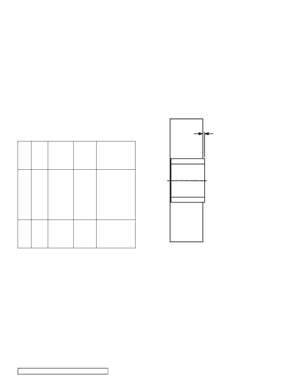
FIGURE 11
IDLER AND BUSHING ASSEMBLY
NOTE:
The R327A and R4327A (stainless steel) pumps have a
special idler-bushing arrangement.
See Figure 11.
The Carbon Graphite idler bushing extends beyond the idler
face on one side of the idler. This side of the idler is placed
toward the head, which allows the Carbon Graphite bushing
to contact the head and provide clearance between the
stainless steel idler face and the head. The Carbon Graphite
bushing extension is 0.008 – 0.012”
(See Figure 11).
The idler bushing has a high interference fit and must be
installed by heat shrinking. The idler must be heated to 600º
F for 1.5 hours before installing the idler bushing. The idler
bushing is to extend beyond the idler face 0.008 – 0.012”.
Install the idler & bushing over the idler pin placing the side of
the idler with the bushing extension against the head. Adjust
end clearance as stated in
Thrust Bearing Adjustment.
HEAD
THIS
SIDE
ROTOR
THIS
SIDE
BUSHING EXTENSION
BEYOND IDLER FACE
0.012
0.008