Pressure adjustment important, Pressure relief valve instructions, Disassembly assembly – Viking Pump TSM630.3: N-RS Universal Seal User Manual
Page 11: Heat cartridges, Warning
SECTION TSM 630.3
ISSUE
H
PAGE 11 OF 13
If a new spring is installed or if pressure setting of pressure
relief valve is to be changed from that which the factory has
set, the following instructions must be carefully followed.
1. Carefully remove valve cap, which covers adjusting
screw.
In ordering parts for pressure relief valve, always give
model number and serial number of pump as it appears on
nameplate and name of part wanted. When ordering springs,
be sure to give pressure setting desired.
PRESSURE ADJUSTMENT
IMPORTANT
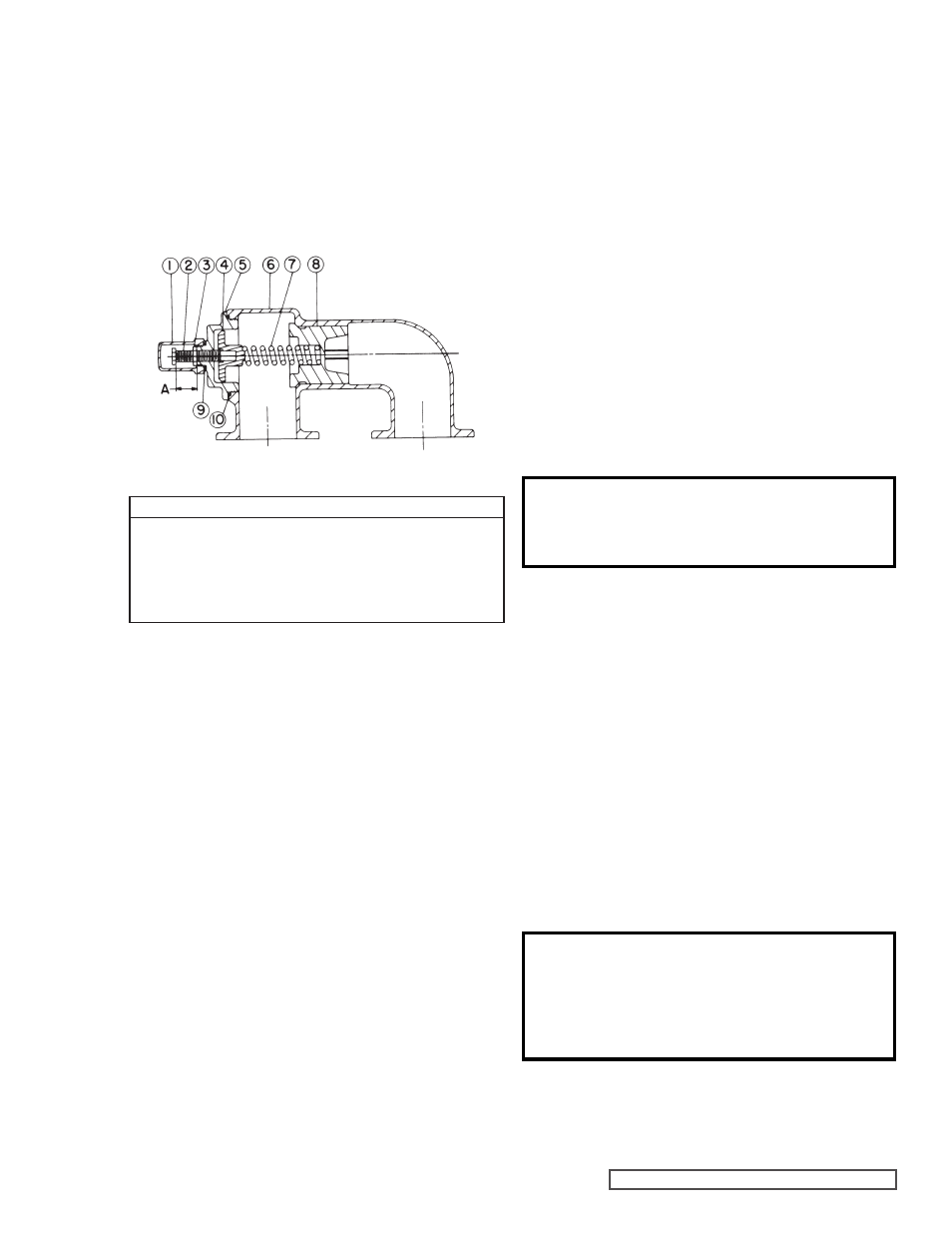
FIGURE 12
PRESSURE RELIEF VALVE
INSTRUCTIONS
VALVE - LIST OF PARTS
1. Valve Cap
6. Valve Body
2. Adjusting Screw
7. Valve Spring
3. Lock Nut
8. Poppet
4. Spring Guide
9. Cap Gasket
5. Bonnet
10. Bonnet Gasket
Mark valve and head before disassembly to insure proper
reassembly.
1. Remove valve cap.
2. Measure and record length of extension of adjusting
screw.
Refer to “A” on Figure 12.
3. Loosen locknut and back out adjusting screw until spring
pressure is released.
4. Remove bonnet, spring guide, spring and poppet from
valve body. Clean and inspect all parts for wear or
damage and replace if necessary.
Reverse procedures outlined under Disassembly. If valve
is removed for repairs be sure to replace in same position.
Relief valve adjusting screw cap must always point towards
suction side of pump. If pump rotation is reversed, remove
relief valve and turn end for end.
DISASSEMBLY
ASSEMBLY
NOTE:
The “RS” size pumps
use a two idler and bushing
arrangement.
For RS327A and RS4327A pumps using non-galling stainless
steel alloy (770) material idlers, the bushings are installed
flush with the idler face.
INSTALLATION INSTRUCTIONS:
WARNING !
The pump needs to be properly grounded
before the heat cartridges are installed.
1. Spacers should be installed between the foot of the
pump and the base. This will create an air gap between
the pump and base to limit heat transfer to the base.
2. Coat the threads of the heat cartridge with an anti-seize
compound prior to installation. Install heat cartridges into
the tapped ports on the head and bracket in the locations
shown in
Figure 13 below. Figure 13 also shows the
location for the thermocouple. The number of heaters
used and the total wattage for each pump size is given in
Table 1 below. ¾” heat cartridges should be tightened to
20 ft-lbs.
3. Viking recommends installing a closed loop temperature
controller with a control algorithm that will minimize or
prevent overshooting the set point temperature. The set
point temperature needs to be slightly higher than the
melting point and significantly lower than the flash point
or boiling point of the liquid being pumped. Viking does
offer a controller for use with our heat cartridges. Ask
your local Viking distributor for details.
2. Loosen locknut (which locks adjusting screw so pressure
setting will not change during operation of pump).
3. Install a pressure gauge in discharge line for actual
adjusting operation.
4. Turn adjusting screw in to increase pressure and out to
decrease pressure.
5. With discharge line closed at point beyond pressure
gauge and pump running, gauge will show maximum
pressure that the valve will allow (full bypass).
WARNING !
Setting the set point temperature higher
than necessary will not make the pump
heat any faster and will shorten the life
of the heat cartridges.
4. Properly insulate the pump to minimize heat loss.
The pump will not heat properly if it is not insulated.
This section applies to 324E Series only.
HEAT CARTRIDGES