Danger – Viking Pump TSM630.3: N-RS Universal Seal User Manual
Page 12
SECTION TSM 630.3
ISSUE
H
PAGE 12 OF 13
NOTE:
1. Heat cartridges, temperature probes, and controllers
must be wired by a licensed electrician to meet local
codes.
2. Heat cartridges require 240VAC, 1 Phase, 60 Hz or
220VAC, 1 Phase, 50 Hz power supply.
DANGER !
• Always disconnect, lockout, and tag
out supply circuits prior to installing.
• The installation must comply with
standard and local regulations.
• All wiring should be done by a licensed
electrician to meet local codes.
• Study this manual thoroughly before
installing and using the heat cartridges.
• Pay special attention to this section
and the parts marked “WARNING!” or
“DANGER”.
• Should questions or uncertainties
arise, please contact your authorized
Viking distributor.
Failure to follow these instructions may
cause an electrical shock and/or sparks,
which may result in serious injury or death.
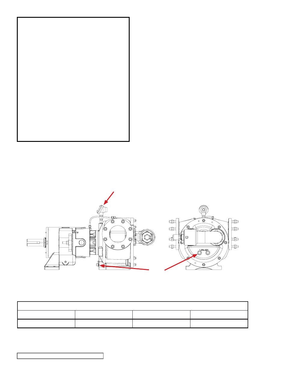
FIGURE 13 - HEAT CARTRIDGE AND THERMOCOUPLE LOCATIONS
TABLE 1 - NUMBER OF HEAT CARTRIDGES IN EACH PUMP MODEL
Wattage By Pump Size
Pump Size
Numbers of Heaters in Head
Number of Heaters in Bracket
Total Wattage
N
2
2
2500
3. Heat cartridges are UL, CSA, & CE marked, RoHs
compliant.
4. Heat cartridges and cables are water resistant but not
water proof. They need to be installed in a protected
area.
5. To make sure that the liquid within the pump is melted
and to avoid damage to the pump, do not start the pump
until the set point temperature has been reached.
6. Several factors such as the size of pump, the set point
temperature, and the insulation will affect the amount
of time it will take for the pump to reach the set point
temperature. Typically it will take 3-4 hours for the pump
to reach its set point temperature.
7. Do not use heat cartridges with different watt densities
from those supplied by Viking. Changing watt densities
may result in localized over or under heating.
8. The thermocouple or temperature probe must be
installed in the bracket location shown in
Figure 13
below. Any other location may result in localized over or
under heating.
9. Please see TSM 630.4 for technical information on the
Viking supplied controller for the heat cartridges.
10. The wires for the heat cartridges can be joined together
in a junction box, and a single wire from the junction box
can be connected to the controller.
11. WARNING Heat cartridges will be hot. Do not touch
pump or heat cartridges until they have been allowed
to cool.
THERMOCOUPLE
HEAT
CARTRIDGES