Assembly, Abearing housing, Danger – Viking Pump TSM230: Hygienic Series User Manual
Page 7
SECTION TSM
230
ISSUE
B
PAGE 7 OF 15
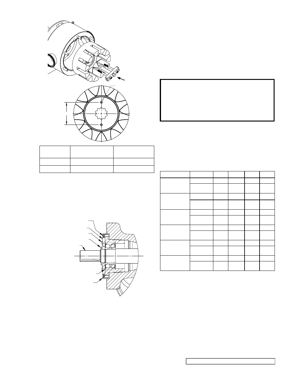
FIGURE 6
ROTOR REMOVAL
A
2X H
GEAR PULLER
Pump Size
Hole Spacing ‘A’
(inch)
Thread Size ‘H’
(inch)
H, HL
1 - 3/4
1/4 - 20
KS-LS
2 - 1/2
1/4 - 20
17. Loosen the two setscrews in the face of the bearing
housing and turn the thrust bearing assembly counter-
clockwise with a pin type spanner wrench and remove
from bracket.
See Figure 7.
ASSEMBLY
DANGER !
BEFORE STARTING PUMP, BE SURE ALL
DRIVE EQUIPMENT GUARDS ARE IN PLACE.
FAILURE TO PROPERLY MOUNT GUARDS
MAY RESULT IN SERIOUS INJURY OR DEATH.
It is recommended that new O-rings be used for reassembly
of the pump.
All O-rings should be lightly lubricated with an appropriate
lubricant that is suitable for the application before installing.
The fastener torque values are listed in
Table 1. Use food
grade anti-seize when installing all fasteners except for the
locknut.
FIGURE 7
THRUST BEARING ASSEMBLY
A
A
BEARING HOUSING
SHAFT
LOCKNUT
OUTER BALL BEARING
BEARING HOUSING
SET SCREW
CAPSCREW
END CAP
18. Disassemble the thrust bearing assembly by removing
the outer ball bearing.
See Figure 7.
19. Clean all parts thoroughly and examine for wear and
damage. Check ball bearings, idler bushing, and idler pin
and replace if necessary. The casing should be examined
for wear, particularly in the area between the ports.
Check all other parts for nicks, burrs, excessive wear and
replace if necessary. All O-rings should be replaced.
Make sure bearings are clean, and then check for
roughness. Roughness can be determined by turning
outer race by hand. Replace bearings if necessary.
Be sure the shaft is free from nicks, burrs and foreign
particles that might damage the mechanical seal.
Scratches on the shaft in the seal area will provide
leakage paths under the mechanical seal. Use a fine
emery cloth to remove scratches or sharp edges.
TABLE 1
FASTENER TORQUE VALUES
Description
H-HL KS-KK LQ-LL LS
End Cap
Capscrews
(Button Head)
Thread Size #10-24
#10-24
#10-24
1/4”
Anti-Seize
Torque (ft-lbs)
1-2
1-2
1-2
4-5
Anti-Rotation
Washer Capscrew
(Button Head)
Thread Size
M6
M8
3/8”
3/8”
Anti-Seize
Torque (ft-lbs)
2-3
5-6
13-14
13-14
Rotor Retainer
Thread Size
3/8”
1/2”
1/2”
1/2”
Anti-Seize
Torque (ft-lbs)
30-35
30-35
30-35
30-35
Idler Pin Capscrew
(Button Head)
Thread Size
1/4”
1/4”
3/8”
3/8”
Anti-Seize
Torque (ft-lbs)
4-5
4-5
13-14
13-14
Head Nuts
Thread Size
1/4”
5/16”
3/8”
3/8”
Anti-Seize
Torque (ft-lbs)
4-5
7-8
13-14
13-14
Locknut
Size
N-05
N-07
N-07
N-08
Dry Torque
(ft-lbs)
50-70
100-130 100-130 120-150
ASSEMBLY FOR MECHANICALLY SEALED PUMPS
1. On jacketed pumps, install jacket tubing onto the bracket
by squeezing the tubing between the slots of the bracket
flange. Make sure that the tubing does not extend past the
flange surface and interfere with installation of the casing.
2. Use an arbor press to install the inner single row ball
bearing onto the shaft.
Refer to Disassembly and
Installation of Inner Ball Bearing, page 14. The inner
bearing in this pump is a “Sealed for Life” bearing that has
seals on both sides. This bearing can be installed either
side first and does not need to be packed with grease.