Pump rotation, Warning, Cip-able port options – Viking Pump TSM230: Hygienic Series User Manual
Page 13: Additional options for cop
SECTION TSM
230
ISSUE
B
PAGE 13 OF 15
BARRIER/BUFFER FLUID
FOR DOUBLE SEAL & DOUBLE
O-RING SEAL
WARNING !
PUMPS WITH DOUBLE SEALS AND DOUBLE
O-RING SEALS REQUIRE A LIQUID BARRIER/
BUFFER FLUID. OPERATING A PUMP WITH
A DOUBLE SEAL OR DOUBLE O-RING SEAL
WITHOUT A BARRIER/BUFFER FLUID WILL
DAMAGE THE SEAL AND PUMP PARTS DUE
TO EXCESS HEAT CAUSED BY DRY RUNNING.
THE BARRIER/BUFFER FLUID FOR THE SEAL
MUST BE COMPATIBLE WITH THE PRODUCT
BEING PUMPED AND THE RELEVENT
MATERIALS OF CONSTRUCTION OF THE PUMP.
SPECIAL CONSIDERATION MUST BE GIVEN
TO THE TEMPERATURE LIMITATIONS OF THE
BARRIER/BUFFER FLUID TO ENSURE NO FIRE
OR EXPLOSION HAZARDS ARE CREATED.
1. Pumps with double seals and double O-ring seals require
a barrier/buffer fluid. The barrier/buffer fluid must be
connected and flowing whenever the pump is operated.
2. The barrier/buffer fluid must be supplied at a minimum
flow rate of 0.13 gpm (0.5 lpm).
3. For a buffer fluid, the fluid should be unpressurized
4. For a barrier fluid, the fluid pressure must be a minimum
of 15 psi (1 bar) greater than the maximum pressure
behind the rotor. Due to the casing groove, the pressure
behind the rotor is equal to the suction pressure for the
pump’s primary rotation and the discharge pressure for
the opposite rotation.
FIGURE 19
DOUBLE O-RING SEAL STATIONARY MEMBER
CAP SCREW FOR
ANTI-ROTATION
WASHER
ANTI-ROTATION WASHER
CASING
SEAL HOUSING
SEAL HOUSING O-RING
BARRIER/BUFFER FLUID CONNECTIONS
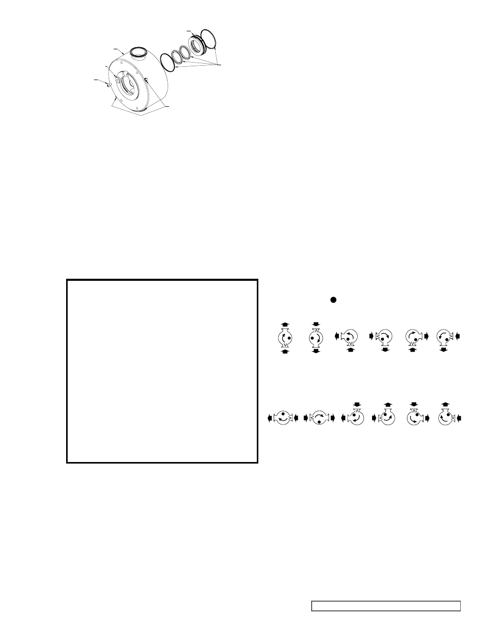
Stationary Member Installation (FIGURE 19):
1. Install the four seal housing O-rings into the seal housing.
2. Install the seal housing into the casing. When installing
the seal housing into the casing, the anti-rotation cut out
of the seal housing must line up with the anti-rotation
washer on the backside of the casing.
PUMP ROTATION
FIGURE 20
PUMP ROTATION
CIP-able Port Options
one port oriented downwards for drainability
Additional Options for COP
Idler pin (shown as ) and rotation shown
is as viewed from shaft end of pump.
Hygienic Series pumps have a primary direction of rotation
with an integral suckback groove to cool and lubricate the seal.
The port with the casing groove must be used as the suction
port for the pump’s primary rotation. Pumps may be operated
in the opposite direction for short periods of time such as for
stripping the line before cleaning. Running the pump in the
opposite direction turns the casing groove into a flush groove,
which causes the area behind the rotor and the seal to be
subjected to the discharge pressure. Pressure protection
must be provided downstream of the pump, regardless of
rotation, or damage to the pump or drive may result.
The port with a casing groove (shown as V) needs to be used
as the suction port for the pump’s primary rotation. Due to the
casing groove location, orientations C, F, J and K will require
a special casing.
A
G
B
H
C
I
D
J
E
K
F
L
5. To obtain maximum seal life, use cool, clean barrier/
buffer fluid. Use warm or hot barrier/buffer fluid if the
pumped product sets up at room temperature.
6. The barrier/buffer fluid connections are shown in
Figures 13 and 19. The NPT connection sizes for the
barrier/buffer fluid are 1/16” for H-HL and 1/8” for KS-
LS. Use the lower connection as the inlet and the higher
connection as the outlet for the barrier/buffer fluid.