Required clearance for disassembly – Viking Pump TSM230: Hygienic Series User Manual
Page 5
SECTION TSM
230
ISSUE
B
PAGE 5 OF 15
ITEM
NAME OF PART
ITEM
NAME OF PART
ITEM
NAME OF PART
1
Locknut
36A
Rotor
53
Head Alignment Dowel Pin
3
End Cap
36B
Shaft
53A
Large Head Alignment Dowel Pin
3B
Capscrew for End Cap
37
Idler and Bushing Assembly
64
Stud for Casing
6
Ball Bearing (Outer)
39
Idler Pin
71
Rotor Retainer Cap O-ring
7
Bearing Housing
39A
Idler Pin Dowel Pin
72
Rotor Retainer Cap
7A
Set Screw
39B
Idler Pin O-ring
73
Rotor Retainer O-ring
19
Seal (Not Shown)
39C
Capscrew for Idler Pin
74
Rotor Retainer
20
Ball Bearing (Inner)
40
Head
75
Capscrew for Anti-Rotation Washer
27
Bracket
41
O-ring for Jacket Head Plate
76
Anti-Rotation Washer
30
Pipe Plug
42
Jacket Head Plate
80
Jacket Tubing for Bracket
31
Casing
43
Stud for Head
35
Head O-ring
44
Nut for Head
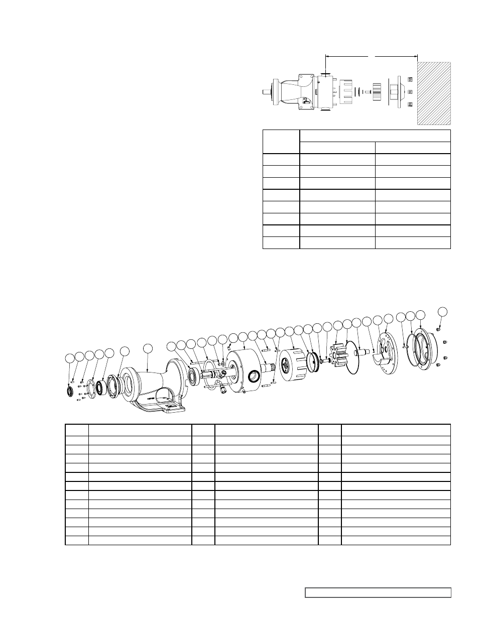
FIGURE 4
EXPLODED VIEW FOR HYGIENIC SERIES MODELS
1 7A
3B
6
7
27
20
36B
64
75 76
31
30
43 53
36A 71 72
73 74 37
35 39
3
39B
36B
53A
39A
40
44
39C 41 42
80
Pump
Size
Required to Remove Pump Internals (AA)
Inch
mm
H
14-1/4
362
HL
15-1/2
394
KS
19-1/4
489
K
19-3/4
502
KK
20-3/4
527
LQ
23
584
LL
24
610
LS
24-3/4
629
REQUIRED CLEARANCE FOR
DISASSEMBLY
FIGURE 3
CLEARANCE FOR DISASSEMBLY
AA
5. Ensure that the cleaning solution is compatible with all of
the pump materials.
SOILED ROTOR RETAINER CLEANING PROCEDURES:
1. Use steps 1, 4 and 6-8 from the disassembly procedures
to remove the rotor retainer components.
2. If rotor retainer blind tapped hole is soiled, submerge
and soak rotor retainer for 5 minutes in Clean Out of
Place tank with suitable cleaning solution.
3. Scrub both external and internal threads with appropriate
bristle brush and suitable cleaning solution.
4. Rinse with clean water and dry blind tapped hole with
clean air.
5. Use new O-rings when reassembling the pump. For
mechanically sealed pumps, follow steps 27 and 29-31
from the assembly procedures to reassemble the pump.
For O-ring sealed pumps, follow steps 13 and 15-17
from the assembly procedures to reassemble the pump.
As long as the thrust bearing was not adjusted, the end
clearance should still be set correctly. Verify the end
clearance and adjust if necessary before putting pump
back into service. If the locknut needs to be retightened
or the end clearance needs to be adjusted, follow the
complete assembly procedures. Do not tighten the
locknut or make major (> 0.005”) adjustments to the end
clearance of mechanically sealed pumps while the seal
is installed in order to avoid damaging the seal faces.
Note: Install new rotor retainer if debris remains after
cleaning. It is recommended that the rotor retainer O-rings be
replaced every 12 months to maintain a tight seal.