Thrust bearing adjustment, Danger, Warning – Viking Pump TSM230: Hygienic Series User Manual
Page 14
SECTION TSM
230
ISSUE
B
PAGE 14 OF 15
1 2
3
4
5
6
7
8
9
10
11
13
12
14
15
16
17
18
19
20
FIGURE 21
LOCATION OF CASING STUDS
INSTALLATION OF CASING STUDS
DISASSEMBLY & INSTALLATION
OF INNER BALL BEARING
Use
Figure 21 and Table 2 to determine casing stud location
for your casing orientation. You can see the available casing
orientations in
Figure 20. Note: Figure 21 is as viewed from
the head end of the pump and
Figure 20 is as viewed from
the shaft end of the pump.
1. A press must be used for disassembly and installation of
the inner ball bearing.
2. Take care not to damage the spline end of the shaft. If you
must press on the spline end, use a spacer to protect the
spline end.
3. Make sure the inner race of the bearing is properly
supported.
THRUST BEARING ADJUSTMENT
DANGER !
MAKE SURE THAT THE DRIVING MEANS
(MOTOR, TURBINE, ENGINE, ETC.) HAS BEEN
“LOCKED OUT” OR MADE NON- OPERATIONAL
SO THAT IT CANNOT BE STARTED WHILE
WORK IS BEING DONE ON PUMP.
WARNING !
DO NOT TIGHTEN THE LOCKNUT OR
MAKE MAJOR ADJUSTMENTS TO THE END
CLEARANCE OF MECHANICALLY SEALED
PUMPS WHILE THE SEAL IS INSTALLED IN
ORDER TO AVOID DAMAGING THE SEAL
FACES. ONLY MINOR ADJUSTMENTS TO THE
END CLEARANCE OF LESS THAN 0.005” CAN
BE MADE WHILE THE MECHANICAL SEAL IS
INSTALLED.
THE LOCKNUT CAN BE TIGHTENED AND THE
END CLEARANCE CAN BE ADJUSTED ON
PUMPS WITH O-RING SEALS WHILE THE SEAL
IS INSTALLED.
Pump Size
Casing Orientation
(See Figure 20)
Location of Casing
Studs (See Figure 21)
H, HL, LQ,
LL, LS
A & B
2, 9, 12, 19
H, HL, LQ,
LL, LS
G & H
4, 7, 14, 17
KS, K, KK
A
1, 10, 12, 19
KS, K, KK
B
2, 9, 11, 20
KS, K, KK
G
4, 6, 15, 17
KS, K, KK
H
5, 7, 14, 16
All Sizes
C & D
1, 8, 15, 18
All Sizes
E & F
3, 6, 13, 20
All Sizes
I & J
3, 10, 13, 16
All sizes
K & L
5, 8, 11, 18
TABLE 2
LOCATION OF CASING STUDS
1. Loosen the two set screws in the outer face of the bearing
housing and turn the thrust bearing assembly clockwise
until it can no longer be turned by hand. Back off counter-
clockwise until the rotor shaft can be turned by hand with
a slight noticeable drag. This is zero end clearance.
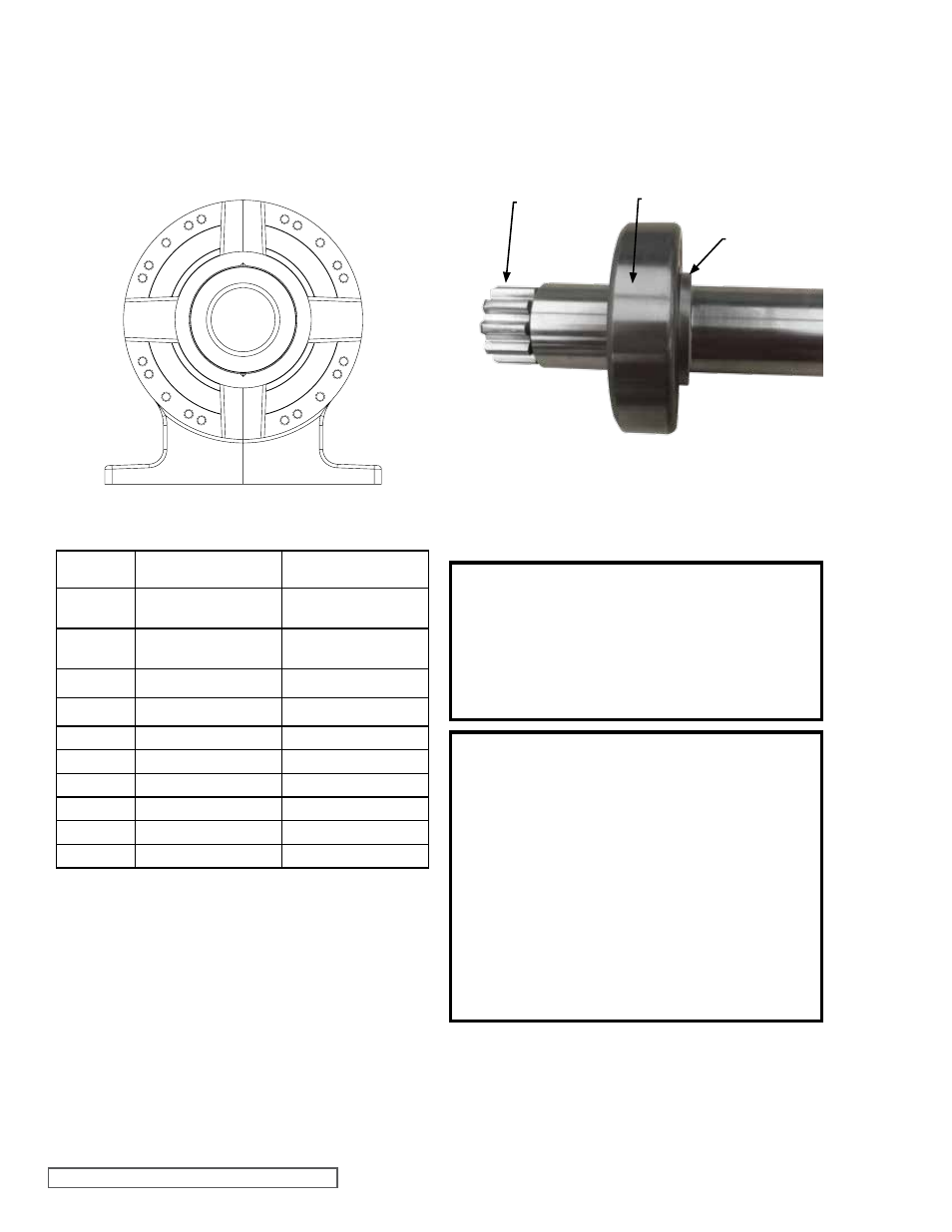
SPLINE END
INNER BEARING
SHOULDER
OF SHAFT
FIGURE 22
INNER SINGLE ROW BALL BEARING
4. Make sure the shaft is perpendicular to the face of the
bearing.
5. Using a food grade lubricant on the inner race and shaft
will help with the installation.
6. Press the bearing onto the shaft until the inner race
contacts the shoulder in the shaft.