Disassembly, Warning, Danger – Viking Pump TSM230: Hygienic Series User Manual
Page 6
SECTION TSM
230
ISSUE
B
PAGE 6 OF 15
1. Remove the head nuts. If pump has a jacketed head
plate, remove the jacketed head plate and O-ring.
Remove head from pump. Jack screw holes (1/4”-20 for
H-KK; 3/8”-16 for LQ-LS) are included to assist with head
removal. Do not allow idler to fall from idler pin. Tilt top of
head back when removing to prevent this. Remove the
head O-ring.
2. After removing the head, use two nuts to hold the casing
in place during disassembly. These nuts should be
located on opposite sides of the casing. A spacer or a
couple of larger nuts will need to be used to compensate
for the unthreaded section of the casing studs. It is
important the casing is secured during disassembly to
avoid damage to the pump internals.
3. Remove the idler pin capscrew. Remove the idler pin,
idler pin dowel pin, and idler pin O-ring. If the idler pin is
difficult to remove from the head, partially thread the idler
pin capscrew back into the idler and use it to dislodge
the idler pin from the head.
4. Insert plastic bar through port opening between rotor
teeth to keep shaft from turning.
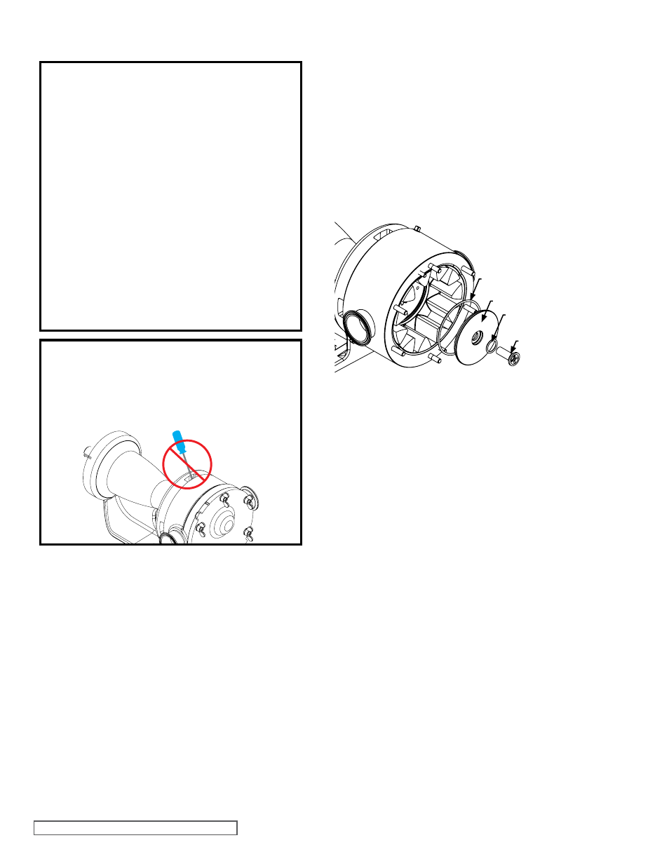
FIGURE 5
ROTOR RETAINER ASSEMBLY
WARNING !
DO NOT INSERT TOOLS IN THE VIEWING
GAPS BETWEEN THE CASING AND BRACKET
OR DAMAGE TO THE SHAFT, SEAL, AND
BEARING WILL RESULT.
ROTOR RETAINER
CAP O-RING
ROTOR RETAINER CAP
ROTOR RETAINER
O-RING
ROTOR
RETAINER
5. For O-ring sealed pumps, remove the end cap of the
bearing housing by removing the end cap capscrews,
and use a bearing locknut socket to turn the locknut
counterclockwise and remove locknut.
See Figure 7.
Do not loosen or remove locknut of mechanically sealed
pumps while the seal is installed in order to avoid
damaging the seal faces. The locknut for mechanically
sealed pumps will be removed in step 11.
6. Use the retainer socket tool to unscrew the rotor retainer.
Turn counter-clockwise to loosen, clockwise to tighten.
7. Remove the rotor retainer O-ring, rotor retainer cap, and
rotor retainer cap O-ring.
See Figure 5. Inspect the rotor
retainer blind tapped hole for contamination. If soiled,
refer to the soiled rotor retainer cleaning procedures.
DISASSEMBLY
8. Remove plastic bar from port opening.
9. Under the rotor retainer cap are two drilled and tapped
holes to assist in the removal of the rotor. These holes
do not extend through the rotor and are not designed for
jackscrews. If the rotor is not removable by hand, use the
gear puller tool in these holes to remove the rotor. Before
using the gear puller tool, reinstall the rotor retainer to
give the gear puller something to push against in order
to avoid damaging the threads for the rotor retainer.
See
Figure 6. The rotary member of the seal will be removed
with the rotor. Take care not to damage the seal components
when removing the rotor. Remove the seal rotary member
after the rotor has been removed from the casing.
10. For mechanically sealed pumps, remove the stationary
face(s) and wave spring(s) from the seal housing. Take
care not to damage the stationary face(s).
11. For mechanically sealed pumps, reinstall the rotor onto the
shaft by lining up the splines on both components. Insert
plastic bar through port opening between rotor teeth to
keep shaft from turning. Remove the end cap of the bearing
housing by removing the end cap capscrews. Use a bearing
locknut socket to turn the locknut counterclockwise and
remove locknut. Remove the plastic bar from port opening.
Remove the rotor from the casing as described in step 9.
12. Remove the two nuts added in step 2. Remove the casing.
13. Remove the seal housing from the casing.
14. Remove the anti-rotation washer from the casing.
15. Remove the shaft from the pump.
16. Remove the inner single row ball bearing from the shaft if
the bearing needs to be replaced.
Refer to Disassembly
and Installation of Inner Ball Bearing, page 14.
DANGER !
Before opening any Viking pump liquid chamber
(pumping chamber, reservoir, etc.) Be sure:
1. That any pressure in the chamber has been
completely vented through the suction or
discharge lines or other appropriate openings
or connections.
2. That the driving means (motor, turbine, engine,
etc.) has been “locked out” or made non-
operational so that it cannot be started while
work is being done on pump.
3. That you know what liquid the pump has
been handling and the precautions necessary
to safely handle the liquid. Obtain a material
safety data sheet (MSDS) for the liquid to be
sure these precautions are understood.
Failure to follow above listed precautionary
measures may result in serious injury or death.