4 connecting power, Connecting power, Figure 6. sentinel interior – Unitec Sentine Installation Manual User Manual
Page 15
S E N T I N E L
Document Number: SENT1001
11
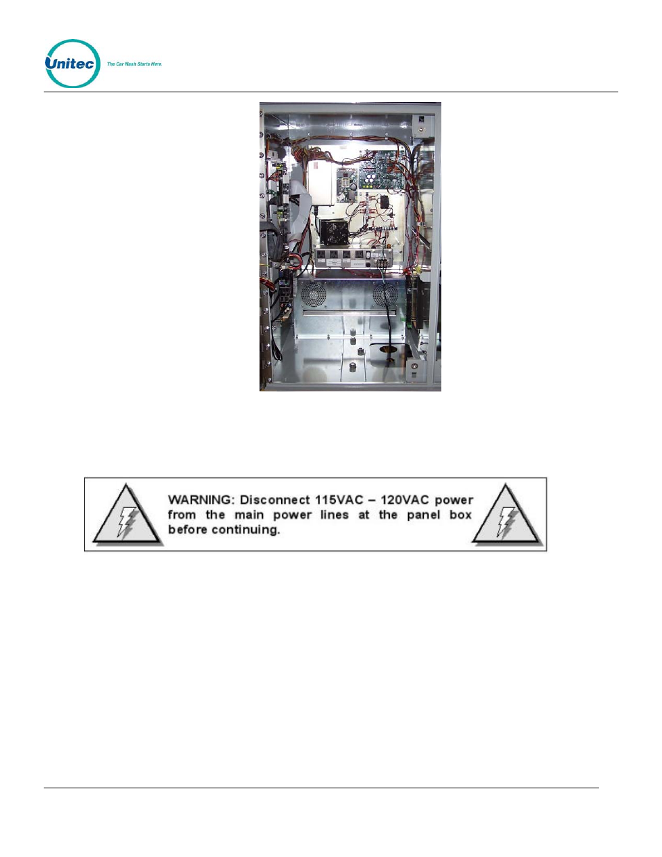
Figure 6. Sentinel Interior
3.4 Connecting Power
1. Locate main power wires. There will be three 16 AWG (or greater) environmentally rated black,
white, and green colored wires.
2. Route the main power wires up through the conduit to the Sentinel’s power panel. Remove excess
wire length, leaving sufficient length to reach the power panel. Remove the plastic shield on the
power terminal block.
3. Secure the Neutral (White), Ground (Green), and Line (Black) wires to the appropriate terminal
screws on the power panel. (See figure below). Re-tighten the screws to hold the wires in place.
Document Name: Sentinel Installation Manual