Robotic deflection mount, 01 installation – Tweco RDM-2000 User Manual
Page 10
Robotic Deflection Mount
3-6
SM-RDM-2000
inStAllAtion AnD opeRAtion
SECTION 3:
INSTALLATION AND OPERATION
3.01 Installation
1. Remove the RDM mount and the other accessories
from the carton. Check to ensure all the items shown
in Figure 1 are located and identified. If any of the
component parts are missing, please notify the
Welding Distributor or Tweco Products customer
service department (1-800-426-1888).
2. Identify and set the “HOmE” position on the robot.
3. Located on the outer diameter of the RDM adapter
plate is a machined line indicating “HOmE” position.
Position this line to the “HOmE” position on the robot
arm. Using a 5mm allen wrench, insert and tighten
the socket head cap screws furnished with the RDM
adapter plate. Refer to Figure 2.
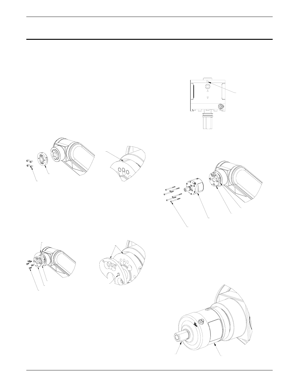
Figure 2: RDM Adapter To Robot Arm
RDM ADApteR
plAte
SOCKET HEAD CAP SCREWS
ALIGN WITH “HOME“
POSITION ON ROBOT
ARM
4. Position and secure the aluminum rear adapter plate
to the RDM adapter plate using the M6 x 1 x 16mm
flat head cap screws. This plate also has a machined
line indicating “HOmE” position. Align this to the RDM
adapter plate machined line. Refer to Figure 3.
RDM ADAPTER PLATE
REAR MOUNTING PLATE
FLAT HEAD CAP SCREWS
SEE DETAIL B
LOCATING
PIN
Align
DetAil b
5. Remove the 7/16”-20 socket head cap screw and flat
washer from the mount shaft on the RDM mount and
set aside.
6. Slide the black protective cover away from the RDM
mount. Insert the M4 x 60mm socket head cap screws
into the holes on the front cover plate.
Figure 3: Rear Mounting Plate
7. Locate the engraved arrows on the side of the mount.
Align the arrows with the “HOmE” line on the rear adapter
plate and place the mount against the plate. The brass
locating pin protruding out from the rear mounting plate
should help locate and position the RDM mount into the
correct position. Refer to Figure 4.
Figure 4: Arrows On RDM Mount
HOME
POSITION
8. Using the 3mm Allen wrench, supplied from the
factory, tighten the M4 x 60mm socket head cap screw
to the rear adapter plate. Refer to Figure 5.
M4 X 60MM SOCKET HEAD CAP SCREWS
RDM-2000 Deflection Mount
REAR ADAPTER PLATE
RDM ADAPTER PLATE
Figure 5: Mounting of RDM Mount
9. Slide the black protective cover back over the mount
shaft and place the 3/16” key stock into the machined
slot on the mount shaft. Refer to Figure 6.
10. If the air assist feature will be used, remove the 1/8” NPT
plug from the side of the mount. Refer to Figure 7.
Figure 6: Key Stock Location
key
rdm deflection mount