Section 4: operation, 01 prewelding procedure, Section 4 – Tweco VS212 Wire Feeder User Manual
Page 29: Operation -1, 01 prewelding procedure -1, Transmig vs 212
TRANSMIG VS 212
Manual No. 0-4949
4-1
OPERATION
SECTION 4:
OPERATION
4.01 Prewelding Procedure
Follow all installation instructions for the welding
power source, the welding gun, and the VS 212 CC/
CV wire feeder before attempting to weld.
1. Make sure all necessary connections have been
made (refer to Connections in the Installation
chapter of this manual).
2. Turn ON the power source and the wire feeder.
3. Set the CC/CV mode switch on the wire feeder to
the proper position (refer to paragraph 12, CC/CV
Mode Switch on page 2-9 and figure 4-1).
High
Low
CC
CV
Art # A-07254
Figure 4-1: CC/CV Switch Location
4. If shielding gas will be used, depress the purge
switch (if equipped) or gun switch and adjust the
flow of gas.
!
WARNING
If the gun switch is depressed, the wire
feeder will feed electrically hot welding
wire. If this hot welding wire touches the
work piece, a welding arc will be
established.
5. Depress the inch switch (if equipped) or gun
switch and adjust the wire feed speed to the
desired value by means of the wire feed speed
control. The wire feed speed control can be
adjusted during setup or while welding.
!
WARNING
If the gun switch is depressed, the wire
feeder will feed electrically hot welding
wire. If this hot welding wire touches the
work piece, a welding arc will be
established.
6. Adjust the voltage control (on a CV machine) or
current control (on a CC machine) to the desired
value. The voltage or current control can be
adjusted during setup or while welding.
7. If using a CV power source, the output contactor
on the power source will have to be energized. In
most cases, this will require a jumper to be added
to the power source or a switch on the power
source to be turned on. Read the power source
owner’s manual for proper connections or settings
required.
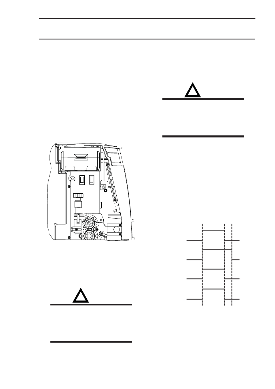
Gun Switch
Gas Valve
Wire Feed
Power Source
ON
ON
ON
ON
OFF
OFF
OFF
OFF
Art # A-05126
Figure 4-2: Functional Timing Diagram