08 front panel controls and connections, 08 front panel controls and connections -6, Transmig vs 212 – Tweco VS212 Wire Feeder User Manual
Page 18
TRANSMIG VS 212
INTRODUCTION
2-6
Manual No. 0-4949
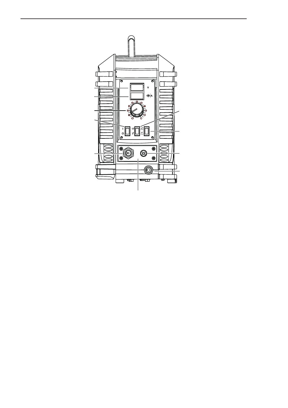
(2) Wire Feed Speed Control
(7) Gun Switch Receptacle
(9) Welding Gun Cable Connection
(10) Removable MIG Gun Cartridge (Tweco style shown)
(3) Wire Feed Speed/Amp Meter
(4) Arc Voltage Meter
(1) On/Off Power Switch
(5) Inch/Purge Switch
(6) 2T/4T Trigger Mode
Selector Switch
(8) Voltage Sensing Receptacle
25mm Dinse
Art # A-07136_AB
1. POWER ON/OFF SWITCH: This switch controls
input power only to the wire feeder and not to the
power source.
2. WIRE FEED SPEED CONTROL: This knob controls
the wire feed speed. The wire feed speed control
can be adjusted during setup or actual welding.
3. WIRE FEED SPEED/AMP METER: The wire feed
speed meter displays the actual wire feed speed
output of the wire feeder. This meter can be
changed to display the actual amperage output of
the power source by adjusting the DIP switches
located on the edge of the display board inside
the unit. Refer to Section 4.07 for details.
4. ARC VOLTAGE METER: The arc voltage meter
displays the actual voltage output of the power
source.
5. INCH/PURGE SWITCH: Depressing the INCH
portion of the switch will feed wire at a speed set
by the WFS control. The wire will not be electrically
hot when using the INCH switch. Depressing the
PURGE portion of the switch will allow shielding
gas to flow out of the welding gun without feeding
wire.
2.08 Front Panel Controls And Connections
6. TRIGGER HOLD SWITCH: This switch selects
either 2 Step or 4 Step gun switch mode.
7. GUN SWITCH RECEPTACLE: The gun switch
receptacle accepts the welding gun control wires.
The gun switch receptacle is where a gun switch
closure is inputted to the wire feeder.
8. VOLTAGE SENSING RECEPTACLE: This receptacle
serves as the voltage sensing point for the wire feeder
and must be connected to the work piece through
the voltage sensing lead for proper operation. If the
voltage sensing lead from the wire feeder and the
weld cable from the power source are not connected
to the work piece, the wire feeder will not work.
9. WELDING GUN CABLE CONNECTION: The welding
gun cable is connected to the wire feeder at this
point. Connections must be tight; otherwise,
arcing or overheating could result.
10.REMOVABLE MIG GUN CARTRIDGE (Patent
Pending): The whole cartridge is interchangeable
to accept competitive types of MIG gun
connections. No external adapters required. See
Appendix 2 and 3 for installation information and
to select the adapter for other MIG Gun styles, ie.
Miller
®
, Lincoln
®
or Euro.
Figure 2-2: Front Panel Controls and Connections