03 adjustment of spool tension, 04 input and output wire guide installation, Transmig vs 212 – Tweco VS212 Wire Feeder User Manual
Page 25
TRANSMIG VS 212
Manual No. 0-4949
3-3
INSTALLATION
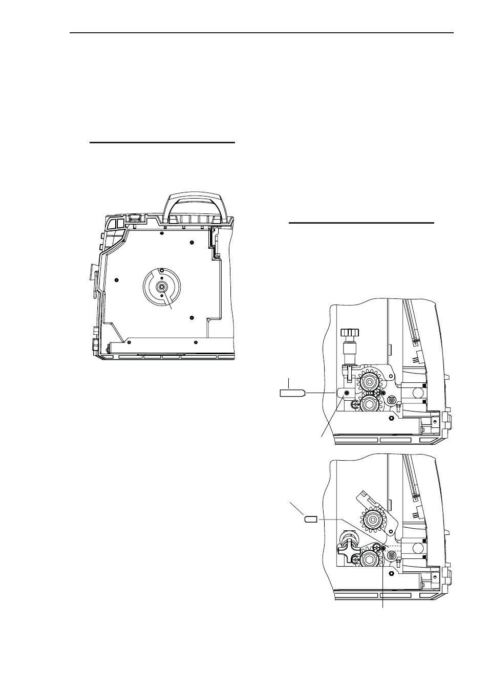
NOTE
Before tightening the input and output
guide lockscrews, install the drive feed roll
to help in the alignment of the wire guides.
Input Wire
Guide
Input Guide
Lockscrew
Output Wire
Guide (inside)
Output Guide Lockscrew
Art # A-07197
3.03 Adjustment Of Spool Tension
Adjust the wire spool tension so the wire will feed
freely into the input wire guide. However, the spool of
welding wire must not coast when wire feeding stops.
To adjust the wire spool tension, tighten or loosen
the hub tension bolt accordingly.
NOTE
Excessive tightening of the hub tension
bolt will result in a shorter motor life.
Hub Tension Bolt
Art # A-07196
Figure 3-3: Hub Tension Bolt
3.04 Input And Output Wire Guide
Installation
1. Install the input wire guide (the longer one) by
loosening the input guide lockscrew and inserting
the guide into the hole in the feedhead assembly.
The recessed end of the guide should be towards
the wire spool. Adjust the guide so that it is clear
of the feed rolls and tighten the input guide
lockscrew.
2. Install the output wire guide (with the conical end
towards the feed rolls) in the same manner as the
input guide. The conical end of the guide should
be as close to the feed rolls as practical. Tighten
the output guide lockscrew.
Figure 3-4: Wire Guide Installation