Section 6: harness adjustment, Proplus auto-darkening welding helmets – Tweco ProPlus Digital Auto-Darkening Welding Helmet User Manual
Page 15
ProPlus Auto-Darkening Welding Helmets
Manual 0-5276
15
SECTION 6: Harness Adjustment
!
WARNING
The helmet comes ready assembled, but before it can be used it must be adjusted to fit the user properly and set up for
delay time, sensitivity and shade level.
ADjUSTING THE FIT OF THE HElMET
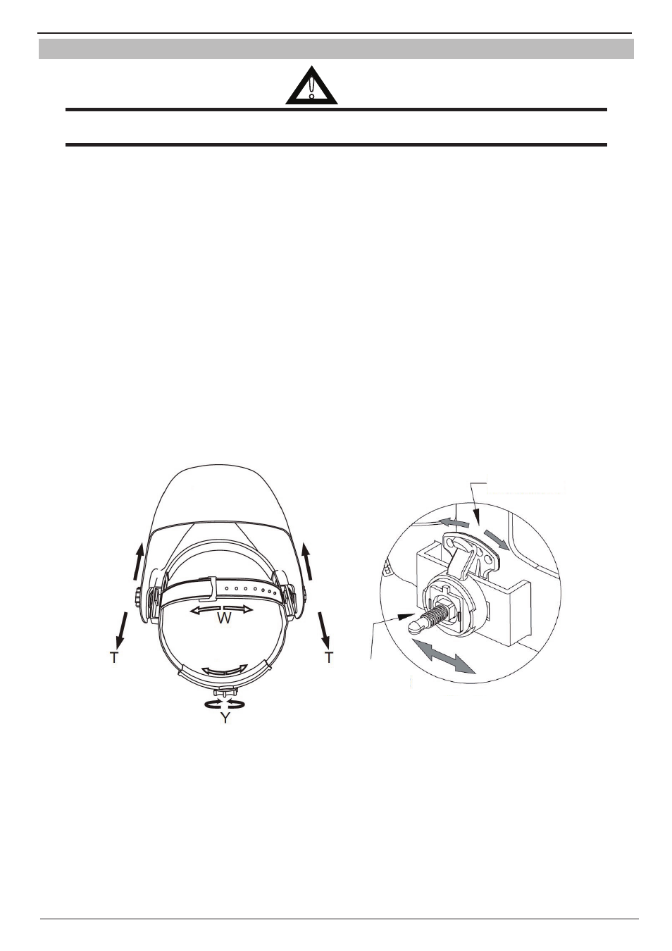
The overall circumference of the headband can be made larger or smaller by rotating the knob on the back of the headband. (See adjust-
ment “Y” in Fig. 6-1). This can be done whilst wearing the helmet and allows just the right tension to be set to keep the helmet firmly
on the head without it being too tight.
• If the headband is sitting too high or too low on your head, adjust the strap which passes over the top of your head. To do this
release the end of the band by pushing the locking stud out of the hole in the band. Slide the two portions of the band to a greater
or lesser width as required and push the locking stud through the nearest hole. (See adjustment “W” in Fig. 6-1).
• Test the fit of the headband by lifting up and closing down the helmet a few times while wearing it. If the headband moves while
tilting, re-adjust it until it is stable.
ADjUSTING THE DISTANCE BETWEEN THE HElMET AND THE FACE
1. Loosen the adjustment knob on both sides of the helmet and slide it closer or further from your face. (See T in Fig. 6-1). It is
important that both eyes are the same distance from the lens. Otherwise the darkening effect may appear uneven.
2. Re-tighten the adjustment knob when adjustment is complete.
ADjUSTING vIEW ANGlE POSITION
TIlT: Tilt adjustment is located on right side of helmet. Loosen the right side headgear tension knob and push the top end of the adjust-
ment lever outward until the lever’s Stop Tab clears the notches. Then rotate the lever forward or back to the desired tilt position. To
adjust the horizontal adjustment slide the harness forward or backward to desired position. Retighten the tension knob to secure into
place. (see Fig. 6-2)
Top
Art # A-11793
Tilt Adjustment
Horizontal
Adjustment
Art # A-11794
Figure 6-1 Harness Adjustment
Figure 6-2 Tilt and Horizontal Adjustment