08 dc bus voltage measurement, Dc bus voltage measurement -7, Transarc 130i – Tweco 130i Transarc Service Manual User Manual
Page 49: 09 dc bus voltage measurement
TRANSARC 130i
Manual 0-5282 6-7
TROUBLESHOOTING
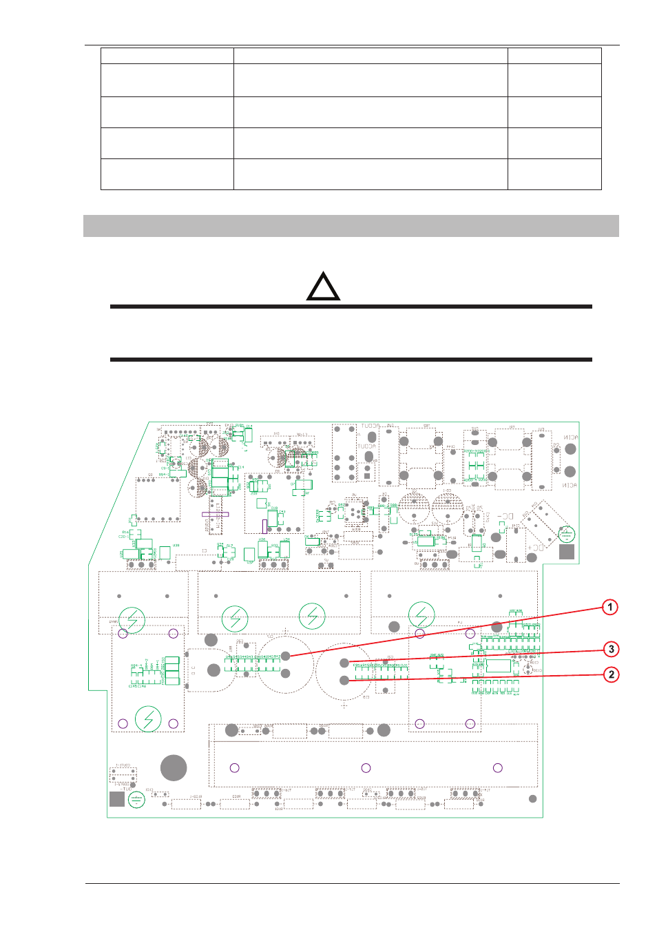
Input Rectifier Testing
Multimeter Lead Placement
Diode Voltage
AC1 to DC+
Positive meter lead to testpoint 17
Negative meter lead to testpoint 18
0.2 – 0.8 VDC
AC2 to DC+
Positive meter lead to testpoint 19
Negative meter lead to testpoint 18
0.2 – 0.8 VDC
AC1 to DC-
Positive meter lead to testpoint 17
Negative meter lead to testpoint 20
0.2 – 0.8 VDC
AC2 to DC-
Positive meter lead to testpoint 19
Negative meter lead to testpoint 20
0.2 – 0.8 VDC
Table 6-7: Input Rectifier, Multimeter set to measure Diode Voltage
6.09 DC Bus voltage measurement
Apply voltage to the Power Source.
!
WARNING
There are extremely dangerous voltage and power levels present inside these Power Sources. Do not
attempt to diagnose or repair unless you have had training in power electronics measurement and
troubleshooting techniques.
Once power is applied to the Power Source, there are extremely hazardous voltage and power levels present.
Do not touch any live parts.
A-11844