04 rear panel (all models), 04 rear panel (all models) -6 – Tweco 500P PowerMaster User Manual
Page 38
POWERMASTER 500, 500P, 350
OPERATION
4-6
Manual No. 0-4749
4.04 Rear Panel (All Models)
St. Louis, MO USA
MADE IN MALAYSIA
WELDING OUTPUT
75V
ENERGY INPUT
50/60HZ
3
U
1
I
1MAX
I
1eff
208 V
230 V
400 V
460 V
88
82
43
39
68
64
33
30
IP23S
50/60HZ
1
AUXILLARY POWER OUTPUT
120 V
24 V
10A
10A
100%
100%
F1
F2
S
5
1
2
3
4
5
Art # A-06859
6
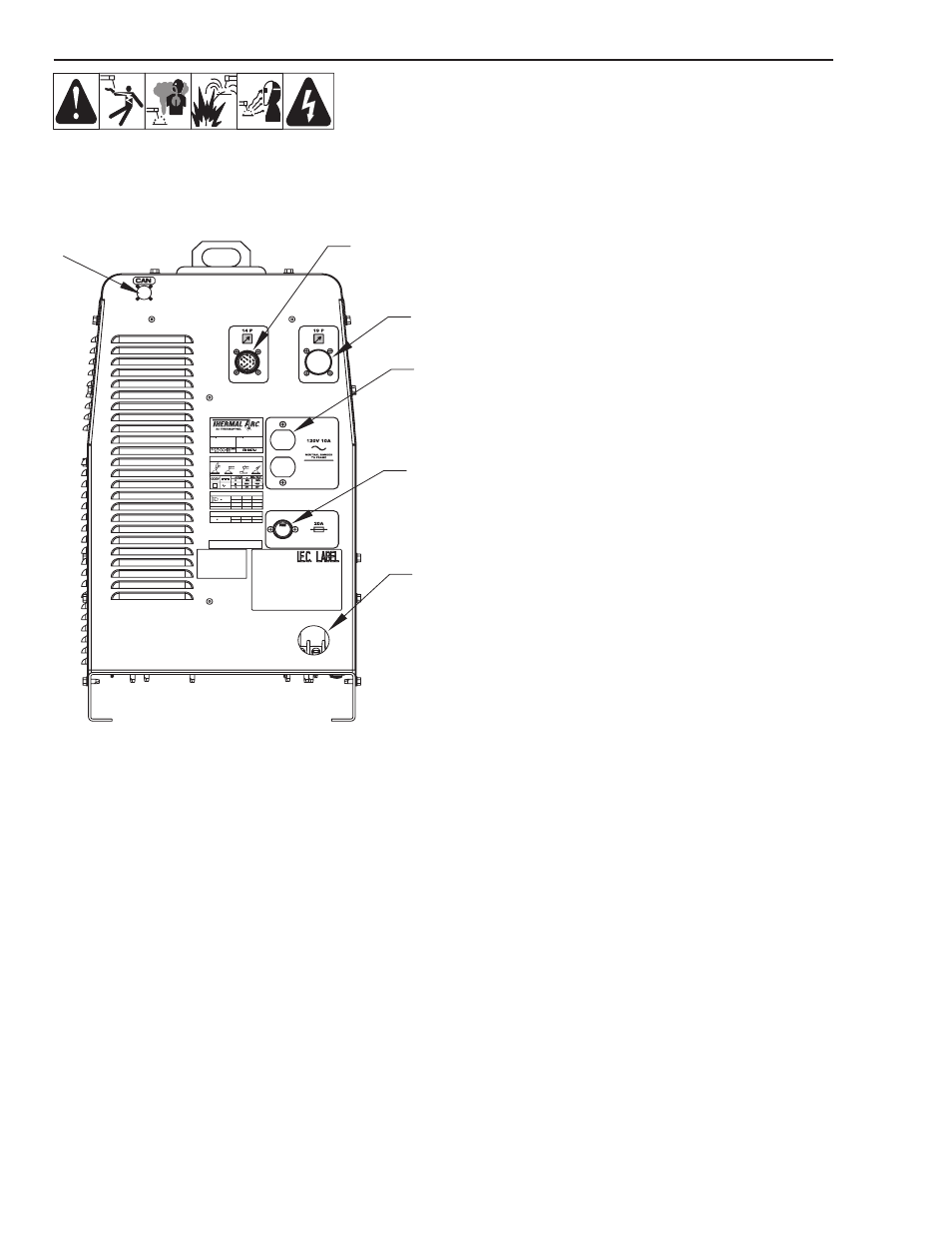
Figure 4-3: Rear Panel
1. 14 Pin Receptacle: This receptacle allows the power
source to interface with wire feeders, and remote
controls such as a foot pedal. This receptacle provides
auxiliary power, contactor control for energizing the
output of the power source, and remote output control.
The pinout is as follows:
A) 24 VAC auxiliary power high side
B) 24 VAC Contactor circuit, (closure between pin A
and pin B will energize output).
C) Remote control maximum (top side of remote
control)
D) Control circuit common
E) Remote control in (wiper of remote pot., 0 to 10
Volts). CV mode: 0 to 10 Volts gives 10 – 44 Volts
of output. CC mode: 0 to 10 Volts gives 5 – 560
Amps of output.
F) Scaled output current signal: Ifb = 100 Amps/Volt
G) 24/115 VAC neutral
H) Output voltage signal: 10 Volts/Volt
I) 115 VAC auxiliary power high side
J) 115 VAC Contactor circuit, (closure between pin I
and pin J will energize output).
K) Chassis ground
L) N/C
M) N/C
N) N/C
2. 19 Pin Receptacle: This receptacle allows the power
source to interface with wire feeders, and remote
controls such as a foot pedal. This receptacle provides
auxiliary power, contactor control for energizing the
output of the power source, and remote output control.
The pinout is as follows:
A) Contactor circuit (+15 Volts)
B) Contactor circuit in, (closure between pin A and
pin B will energize output).
C) Scaled output voltage signal: Vfb = 10 Arc Volts/
Volt
D) 24 VAC auxiliary power high side
E) 115 VAC auxiliary power high side
F) 24/115 VAC neutral
G) Chassis ground
H) Remote control maximum (top side of remote pot.)
J) Remote control in (wiper of remote pot., 0 to 10
Volts). CV Mode: 0 to 10 Volts gives 0 – 44 Volts
of output. CC Mode: 0 to 10 Volts gives 0 – 560
Amps of output.
K) Remote control minimum (bottom side of remote
pot.)
L) Control circuit common
M) Arc Established = +12 Volts
N) Control circuit common