03 connection instructions, 04 connecting welding machine to line voltage – Tweco 500P PowerMaster User Manual
Page 26
POWERMASTER 500, 500P, 350
INSTALLATION
3-2
Manual No. 0-4749
3.04 Connecting Welding Machine to
Line Voltage
The input power should be connected to the unit through
a fused disconnect switch, or other suitable
disconnecting means furnished by the user. Access is
provided in the rear panel of the machine for the entry of
the input conductors.
DANGER:
ELECTRIC SHOCK CAN KILL.
Open the disconnect switch, or breaker, and
determine that no voltage is present, before
connecting wires between welding machine and
power supply.
CAUTION:
The method of installation, conductor size, and
overcurrent protection shall conform to the
requirements of the local electrical code, the
National Electrical Code, or other national
codes, as applicable. All installation wiring and
machine reconnection shall be done by
qualified persons.
Tables 3-1 and 3-2 provide minimal information for
selection of line conductors, fuses, and the equipment
grounding conductor. This information is from the
National Electrical Code NFPA 70-1981 Edition. Install this
equipment per the latest edition, available from the
National Fire Protection Association, Batterymarch Park,
Quincy, MA 02269.
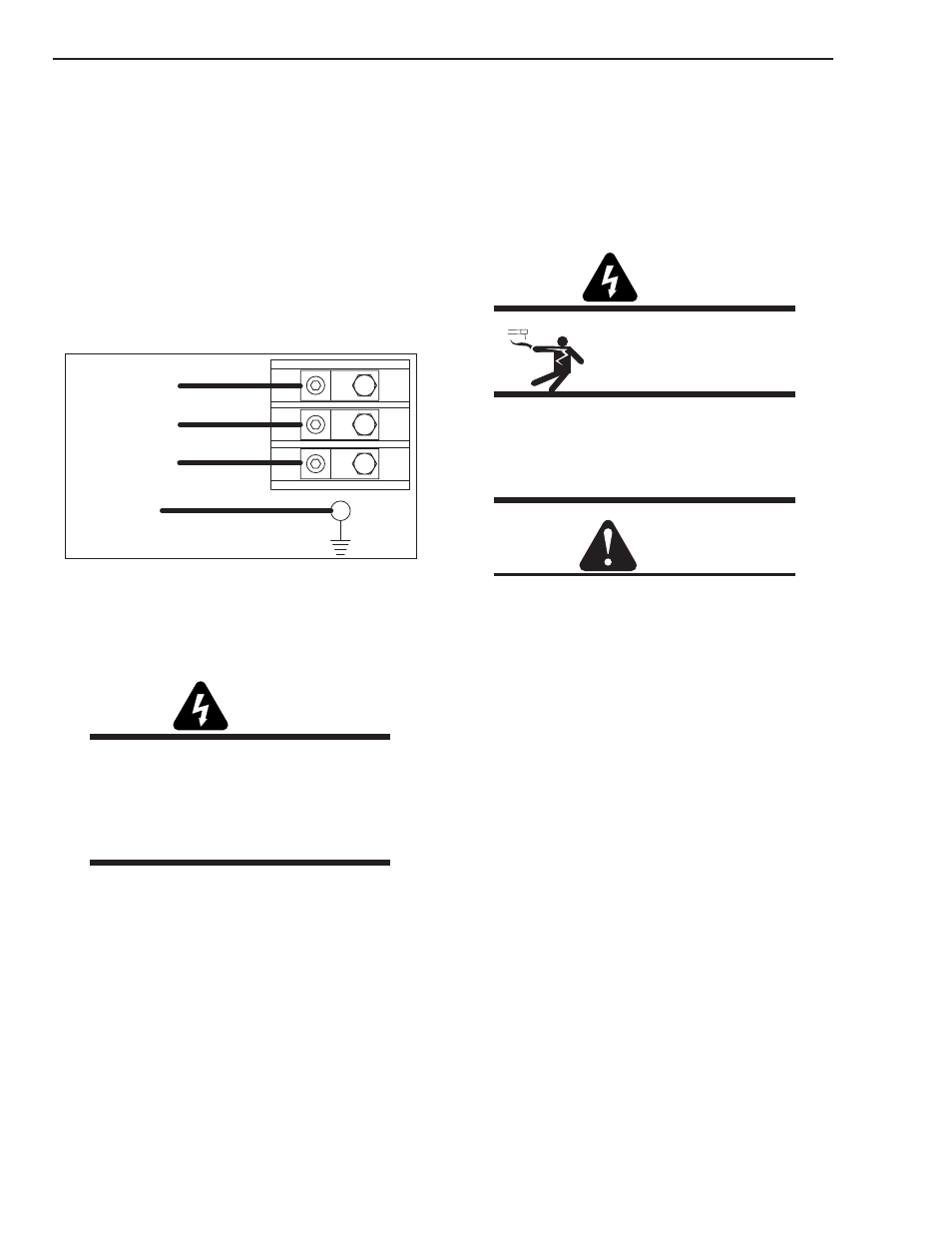
3.03 Connection Instructions
1. Remove left side panel to gain access to the input
terminal block and ground screw.
2. Connect the three phase power line to the
terminal block as shown in Figure 3-5.
3. Connect the power system safety ground to the
screw labeled FRAME GROUND located on the
base of the machine near the input terminal block
as shown in Figure 3-5.
4. Replace side panel.
CUSTOMER
INPUT
LINES
FRAME GROUND
L3
L2
L1
Art # A-04100
Figure 3-5 Input Terminal Block
WARNING:
Never connect the safety ground screw to one
of the three line phases. This would represent a
serious electrical shock hazard. The wiring to
this machine should be performed by a qualified
person only.