Fabricator 251 – Tweco 251 Thermal Arc Fabricator User Manual
Page 43
FABRICATOR 251
Manual No. 0-4847
4-5
OPERATION
Positive and Negative Welding Current Terminals
Refer back to Figure 4-1. Both terminals located at
the bottom of the unit are shown without the terminal
knob. Both knobs must be firmly secured before at-
tempting to weld.
Gun Polarity Lead
This lead selects the welding voltage polarity of the
electrode wire. Attach it to the positive welding termi-
nal (+) when using steel, stainless steel or aluminium
electrode wire . Attach the Gun Polarity Lead to the
negative welding terminal ( - ) when using gasless
flux cored electrode wire. If in doubt, consult the
manufacturer of the electrode wire for the correct
polarity. Also refer to section 3-15.
Positive and Negative Welding Terminal Knobs
Welding current flows from the Power Supply via
heavy duty terminals. It is essential, that these termi-
nal knobs are tight to achieve the necessary electrical
connection.
CAUTION
Loose welding terminal connections can cause
overheating and result in failure of the termi-
nals.
Gun Switch Receptacle
The Torch Trigger 4-pin receptacle is used to connect
the two wires from the torch gun to the Fabricator
251. Only pins 1 and 2 are used for this.
To make connections, align keyway, insert plug, and ro-
tate threaded collar fully clockwise.
1
2
Art # A-07171
Figure 4-3: Gun Switch Receptacle
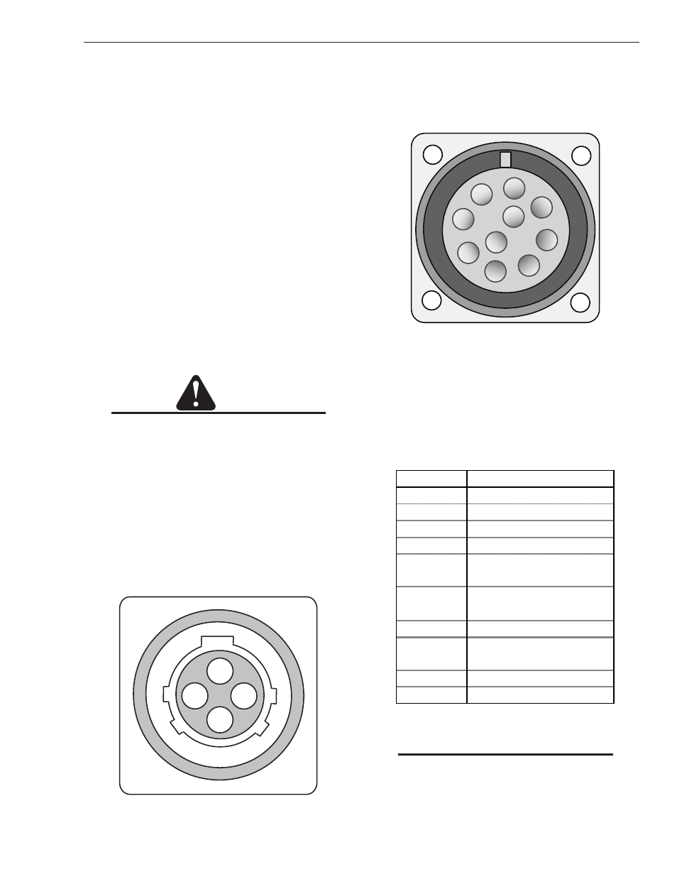
Spool Gun Interface Amphenol Connector
The Spool Gun Interface 10 pin connector is used to
connect a spool gun to the Fabricator 251 (refer to
Figure 4-4 and Table 4-1).
A
B
C
D
J
I
E
F
G
H
Art # A-07181
Figure 4-4: Spool Gun 10 pin Receptacle
To make connections, align keyway, insert plug, and
rotate threaded collar fully clockwise. The socket in-
formation is included in the event the supplied cable
is not suitable and it is necessary to wire a plug or
cable to interface with the SPOOL GUN 10-pin recep-
tacle.
Socket Pin
Function
A
Not Used
B
Spool Gun Motor (-)
C
Spool Gun Motor (+)
D
Spool Gun Switch
E
Spool Gun Speed C.W.
Potentiometer
F
Spool Gun Speed Wiper
Potentiometer
G
Spool Gun Switch
H
Spool Gun Speed C.C.W.
Potentiometer
I
Not Used
J
Not Used
Table 4-1: 10-pin Receptacle Pin Functions
NOTE
When the SPOOL GUN is properly attached
and the trigger is depressed, the system au-
tomatically disables the internal wire feed and
gas control and selects the SPOOL GUN feeder
and gas control.