Operation arc master 175 te – Tweco 175 TE Arcmaster User Manual
Page 31
oPeration
arc master 175 te
Manual 0- 5116 4-3
Operation
a. Power on indicator
The Power ON Indicator illuminates when the ON/OFF
switch is in the ON position and the correct mains
voltage is present.
B. over Heat indicator
The welding power source is protected by a self
resetting thermostat. The indicator will illuminate if the
duty cycle of the power source has been exceeded. If
the Over Heat light illuminates wait for the Over Heat
light to extinguish before resuming welding.
c. trigger mode selection switch (tiG mode only)
normal mode
Press the TIG Torch Trigger Switch and hold depressed
to weld. Release the TIG Torch Trigger Switch to stop
welding. Downslope operates in TIG mode only. Whilst
welding if the TIG Torch Trigger Switch is released, the
welding current ramps down to zero current over a
defined period of time. The time period is determined
by the Downslope Control Knob (F).
Latch mode
This mode of welding is mainly used for long weld
runs. The operator need only to press the TIG Torch
Trigger Switch to activate and then release the TIG
Torch Trigger Switch to continue to weld, then press
the TIG Torch Trigger Switch again and release the TIG
Torch Trigger Switch to stop welding. This eliminates
the need for the operator to depress the TIG Torch
Trigger Switch for the complete length of the weld.
Downslope operates in TIG Mode only. To activate the
Downslope function in Latch mode whilst welding, the
TIG Torch Trigger Switch must be depressed and held
which will ramp the Welding Current down to zero over
a defined period of time. The time period is determined
by the Downslope Control Knob (F). At any time whilst
welding if the TIG Torch Trigger Switch is depressed
and released the arc will extinguish immediately.
D. Process selection switch
Switches between Manual Arc, Lift TIG and HF TIG
modes. Refer to Section 3.08 Setup for Manual Arc
Welding and 3.09 Setup for TIG Welding.
e. Welding current control
The welding current is increased by turning the Weld
Current Control Knob clockwise or decreased by
turning the Weld Current Control Knob anticlockwise.
The welding current should be set according to the
specific application. Refer to application notes in this
section for further information.
f. arc force/Down slope control
Arc Force is effective when in Manual Arc Mode only.
Arc Force control provides an adjustable amount of
Arc Force (or “dig”) control. This feature can be
particularly beneficial in providing the operator the
ability to compensate for variability in joint fit-up
in certain situations with particular electrodes. In
general increasing the Arc Force control toward ‘10’
(maximum Arc Force) allows greater penetration
control to be achieved. Down Slope operates in TIG
mode only. It is used to set the time for weld current
to ramp down. Refer to Item C (Trigger Mode Selection
Switch) for further information regarding Downslope
operation.
G. Gas outlet
The Gas Outlet is a 5/8-18 UNF female gas fitting and is
utilised for the connection of a suitable TIG Torch.
H. Post Gas flow
Post Gas Flow is the time Gas flows after the arc
has extinguished. This is used to cool and reduce
oxidisation of the Tungsten Electrode. Post Gas Flow
time is proportional to the Welding Current. For
example if the Welding Current is set to 10 amps the
Post Gas Flow time will be approximately 3 +0/-1
seconds. For a Welding Current set to 175 Amps the
Post Gas Flow time will be approximately 6 +1/-0
seconds. The Post Gas Flow time cannot be adjusted
independently of the Welding Current.
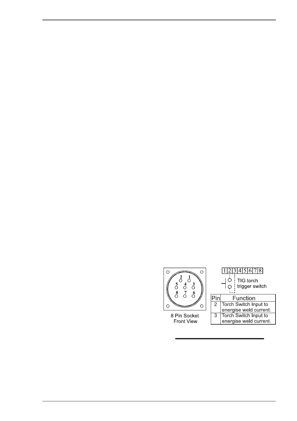
i. torch trigger socket
The 8 pin Torch Trigger Socket is used to connect the
TIG Torch Trigger Switch to the welding Power Source.
To make connections, align keyway, insert plug, and
rotate threaded collar fully clockwise.
Art # A-08956
NOTE:
Remote Welding Current Control is not available
on this model.
J. on/off switch (located on rear panel not
shown)
This switch controls the Mains Supply Voltage to the
Power Source.