Arcmaster, 160 s – Tweco 160 S Arcmaster User Manual
Page 29
ARCMASTER
®
160 S
March 31, 2006
6-1
SECTION 6:
SEQUENCE OF OPERATION
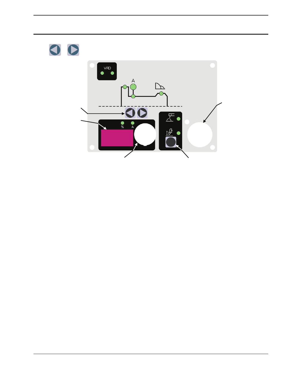
NOTE: Scroll Buttons are used to select the parameters to be set. The LED’s show which
function is being adjusted on the weld sequence graph. Refer to Symbols Table located in
the front of the manual for Symbol descriptions.
3
4
5
1
2
Figure 7-1: 160 S Front Panel
1. Scroll Buttons – used to select the parameter to be set.
The LED’s show which function is being adjusted on the
weld sequence graph.
2. Digital LED display – Welding amperage and parameter
values are displayed in this window. Internal warnings
such as over temperature, low or high input voltage
applied are signaled to the operator by a warning sound
and error message on the screen.
3. Control Knob – allows the operator to adjust the output
amperage within the entire range of the power source,
also used to set each parameter value. Pushing the knob
inward displays the actual welding voltage.
4. Process Button - This button selects between STICK or
LIFT TIG mode.
5. 8 pin remote control receptacle for connecting remote
device. A remote control device is required for use during
LIFT TIG operation. See section 4.01, section 2 “
Remote
Control Socket”, for complete details of the remote
device.
6.01 Stick Welding
• Connect work lead to negative terminal
• Connect electrode lead to positive terminal
• Switch machine on
• Connect remote control device if required
Use the Scroll Buttons to move to the parameter to be set.
The LED will show which function is being adjusted on the
weld sequence graph. Use the control knob to adjust each
parameter.
• Set HOT START
• Set WELD current
• Set Arc Control
Commence welding
6.02 DC Lift TIG Welding
• Connect work lead to positive terminal
• Connect TIG torch to negative terminal
• Switch machine on
• Set WELD current.
• Connect remote control device. A remote control device
is required for use during LIFT TIG operation. See
section 4.01, section 2 “Remote Control Socket
”, for
complete details of the remote device.
Use the Scroll Buttons to move to the parameter to be set.
The LED will show which function is being adjusted on the
weld sequence graph. Use the control knob to adjust each
parameter.
• Set WELD time
Commence welding