04 torch parts selection, 05 cut quality – Tweco SL100 User Manual
Page 26
OPERATION
4-2
Manual 0-2962
Refer to Appendix 1 for a typical detailed block
diagram of Sequence of Operation.
The system is now ready for operation.
4.04 Torch Parts Selection
Depending on the type of operation to be done determines
the torch parts to be used.
Type of operation:
Drag cutting, standoff cutting or gouging
Torch parts:
Shield Cup, Cutting Tip, Electrode and Starter
Cartridge
NOTE
Refer to Section 6 and the Appendix Pages for
additional information on torch parts.
Change the torch parts for a different operation as follows:
NOTE
The shield cup holds the tip and starter car-
tridge in place. Position the torch with the
shield cup facing upward to keep these parts
from falling out when the cup is removed.
1. Unscrew and remove the shield cup assembly from the
torch head.
2. Remove the Electrode by pulling it straight out of the
Torch Head.
Art # A-03417
Electrode
Start Cartridge
Tip
Shield Cup
Assembly
Torch Head
Torch Parts (Drag Shield Cap & Shield Cup Body Shown)
3. Install the replacement Electrode by pushing it straight
into the torch head until it clicks.
4
. Install the starter cartridge and desired tip for the op-
eration into the torch head.
5. Hand tighten the shield cup assembly until it is seated
on the torch head. If resistance is felt when installing
the cup, check the threads before proceeding.
4.05 Cut Quality
NOTES
Cut quality depends heavily on setup and pa-
rameters such as torch standoff, alignment with
the workpiece, cutting speed, gas pressures,
and operator ability.
Refer to Appendix Pages for additional informa-
tion as related to the Power Supply used.
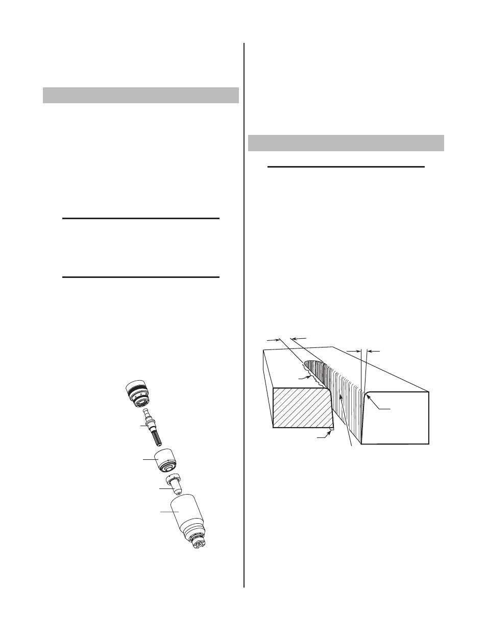
Cut quality requirements differ depending on application.
For instance, nitride build - up and bevel angle may be
major factors when the surface will be welded after cutting.
Dross - free cutting is important when finish cut quality
is desired to avoid a secondary cleaning operation. The
following cut quality characteristics are illustrated in the
following figure:
Kerf Width
Cut Surface
Bevel Angle
Top Edge
Rounding
Cut Surface
Drag Lines
Dross
Build-Up
Top
Spatter
A-00007
Cut Quality Characteristics
A. Cut Surface
The desired or specified condition (smooth or rough)
of the face of the cut.
B. Nitride Build - Up
Nitride deposits can be left on the surface of the cut
when nitrogen is present in the plasma gas stream.
These buildups may create difficulties if the material
is to be welded after the cutting process.