Tweco PAK 10 User Manual
Page 20
Installation
8
Manual No. 0-0515
4FU
5A
INPUT
PLASMA
SEC
3
1
2
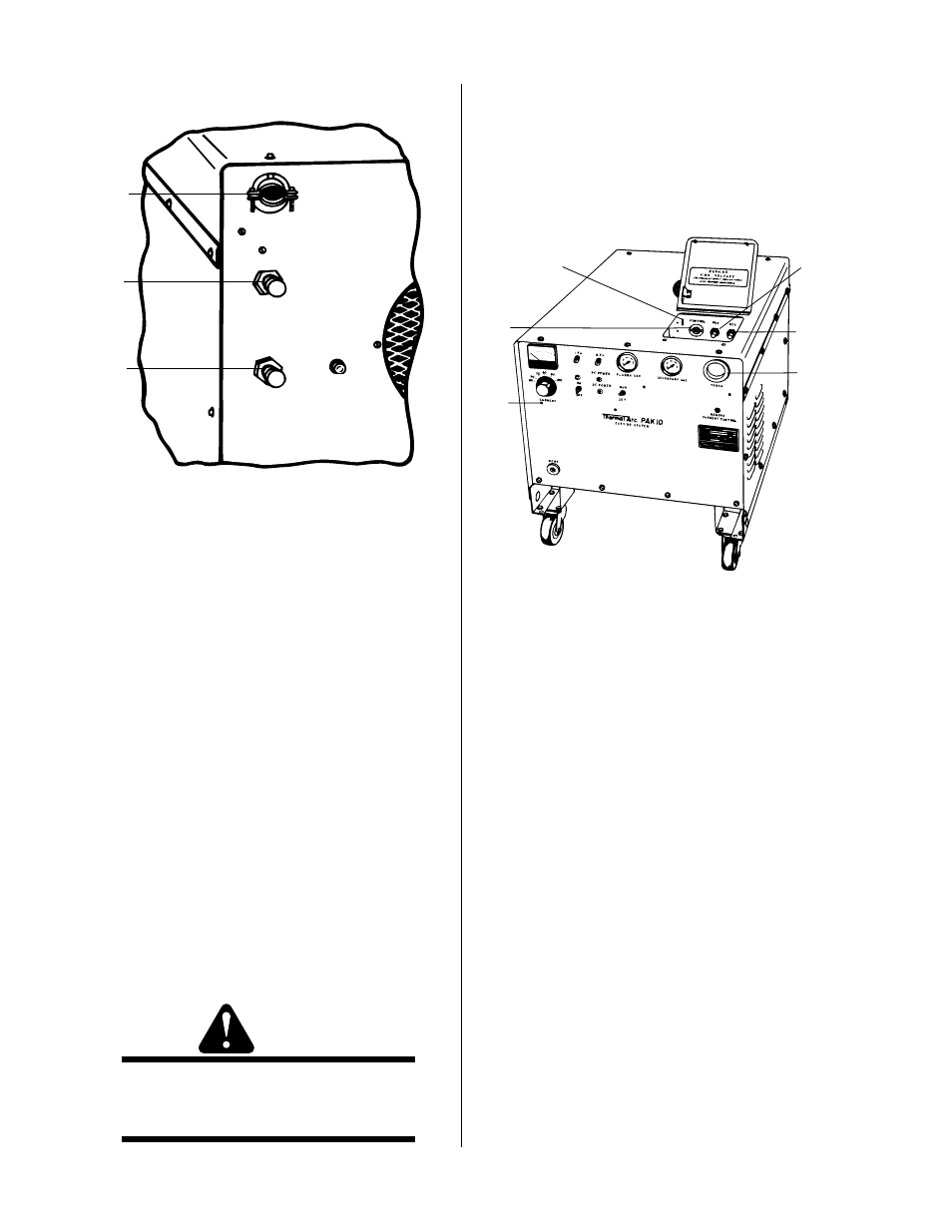
A-03360
1. INPUT cable bushing
2. SECondary gas connection fitting
3. PLASMA gas connection fitting
Figure 2-E Rear Panel Connections
8. Check the torch to see that it is properly assembled
(Refer to Section 4.1.).
a. Pass the torch leads and control wire through
the bushing on the front panel (5, Figure 2-F)
and connect them to the appropriate fittings.
b. If the torch is machine-mounted, the remote
control assembly plug must also be inserted in
the remote current control jack.
9. Re-install the cover of the unit (the leads access door
must be open). Start the sheet metal screws but do
not tighten them until the cover is lined up.
Carefully close the leads access door, making sure
that the switch actuator (1, Figure 2-F) enters its slot
and activates the interlock switch. When the cover
is properly positioned, tighten the screws.
WARNING
Do Not Operate the Unit unless all parts of the
enclosure are in place. This is important for
proper cooling as well as safety.
10. The work cable (Figure 1-A) is equipped with a
twist-lock plug on one end and a work clamp on
the other. The plug fits into the work receptacle on
the front of the unit (8, Figure 2-A) and the clamp
attaches to the workpiece. The unit is now ready
for operation.
3
5
4
1
2
6
A-03361
l. Actuator for Interlock Switch (SW3)
2. Negative (-) torch lead fitting
3. Positive (+) torch lead fitting
4. Torch control switch receptacle
5. Torch lead insulating bushing
6. Remote current control jack
Figure 2-F Torch Connection Access Door and
Panel