Tweco Merlin 6000 Slave PS User Manual
Page 25
Manual 0-2570
3-9
INSTALLATION PROCEDURES
Pilot Resistor Setting vs. Input Line Voltage
Transformer Voltage Range
200-230 VAC
380-460 VAC
500-575 VAC
Input
(VAC)
Ohms
Input
(VAC)
Ohms
Input
(VAC)
Ohms
180
6.5
340
5
450
5.5
190
7.5
350
5.5
460
6
200
8.5
360
6
470
6.5
210
4.5
370
6.75
480
7
220
5.5
380
7.25
490
7.5
230
6.5
390
8
500
8
240
7.5
400
8.5
510
8.5
250
9
410
9
520
4.5
420
4.5
530
5
430
5
540
5.5
440
5.5
550
6
450
6
560
6.5
460
6.5
570
7
470
7
580
7.25
480
7.5
590
7.5
490
8
600
8
500
8.5
610
8.25
510
9
620
8.5
630
9
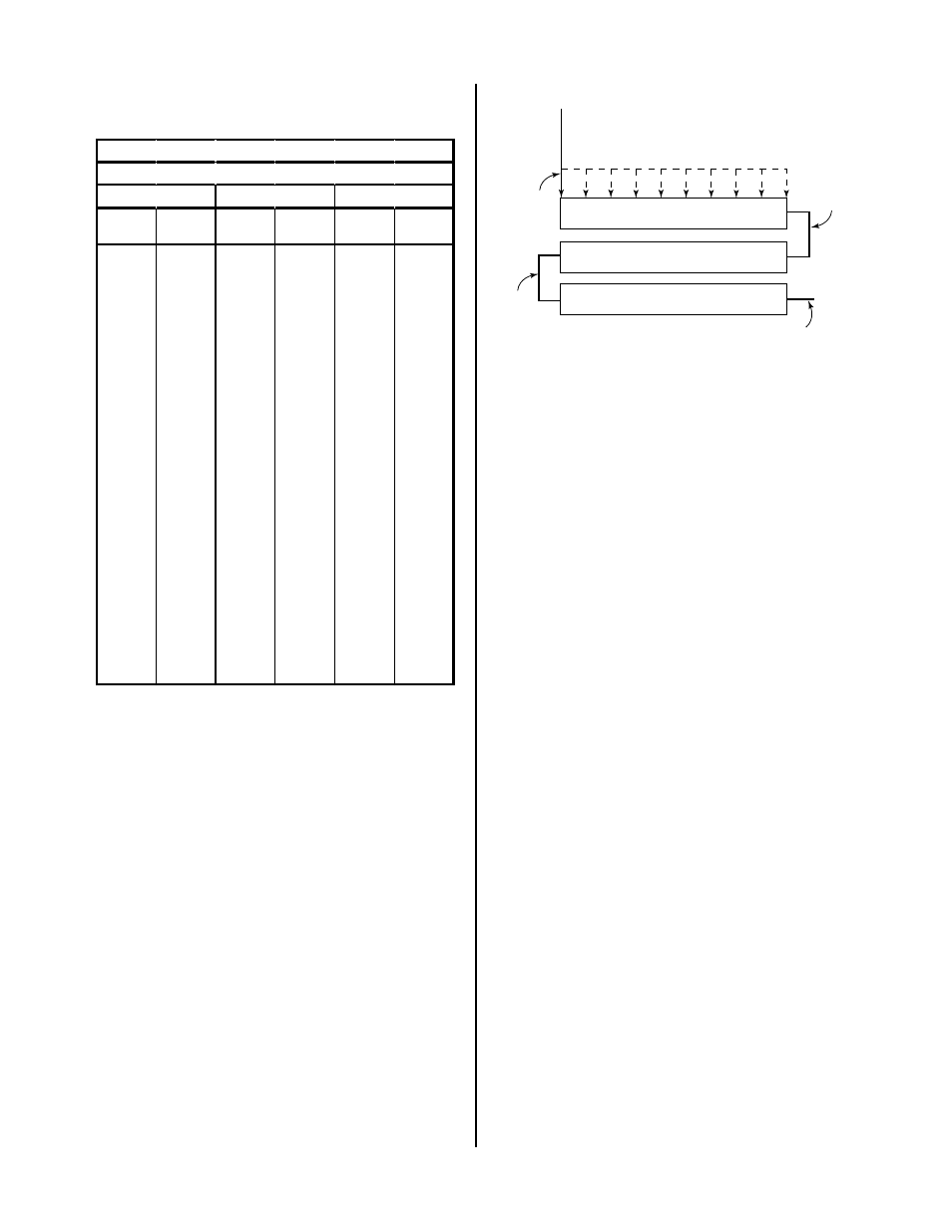
6. Wires are attached to the pilot resistors with metal
clamps or taps. Locate and loosen the screw that
secures the wire #99 tap on resistor R16. Deter-
mine, from the Figure below, the correct position
for the tap on R16 and tighten the screw.
Example:
To set for 6 ohms measure 5” from the right side
of R16, where wire # 96 attaches, and secure the
#99 tap at that position.
Wire #99
Tap
9.0 ohms
At End
R16 (4.5 ohms)
R22 (2.2 ohms)
R21 (2.2 ohms)
Wire
#96A
Wire #74
8.5 ohms
12.8" (305 mm)
8.0 ohms
11.2" (279 mm)
7.5 ohms
9.6" (242 mm)
7.0 ohms
8.1" (203 mm)
6.5 ohms
6.5" (164 mm)
6.0 ohms
5.0" (127 mm)
5.5 ohms
3.4" (87 mm)
5.0 ohms
1.9" (44 mm)
4.4 ohms
At End
Wire #96
A-02598
Figure 4-5 Resistance Value Diagram
7. Test the pilot at 300A output current. If it still
sputters move the wire #99 tap to the right, to-
ward wire #96, 1 inch (25.4 mm) at a time until
the pilot no longer sputters.