07 primary power cable connections – Tweco Merlin 6000 Slave PS User Manual
Page 19
Manual 0-2570
3-3
INSTALLATION PROCEDURES
Input Voltage
Terminal Board
L1
L2
L3
Busbars
A-01558
Extra Busbar
Storage Location
Figure 3-3 Input Voltage Terminal Board Location
NOTE
Extra busbars are attached (stored) to the top side
of the power transformer assembly.
2. Check the busbar configuration on the input volt-
age terminal board . The busbar configuration
must correspond with the available line voltage
per the following figure and the label inside the
unit:
200, 208,
220, or 230
11
12
L3
13
15
14
6
7
L2
8
10
9
1
2
L1
3
5
4
380, 415,
or 460
11
12
L3
13
15
14
6
7
L2
8
10
9
1
2
L1
3
5
4
500, or 575
11
12
L3
13
15
14
6
7
L2
8
10
9
1
2
L1
3
5
4
Busbar Connections For Input Voltages
A-00904
Figure 3-5 Busbar Connections
If necessary, reposition the busbars to correspond to
the available line voltage.
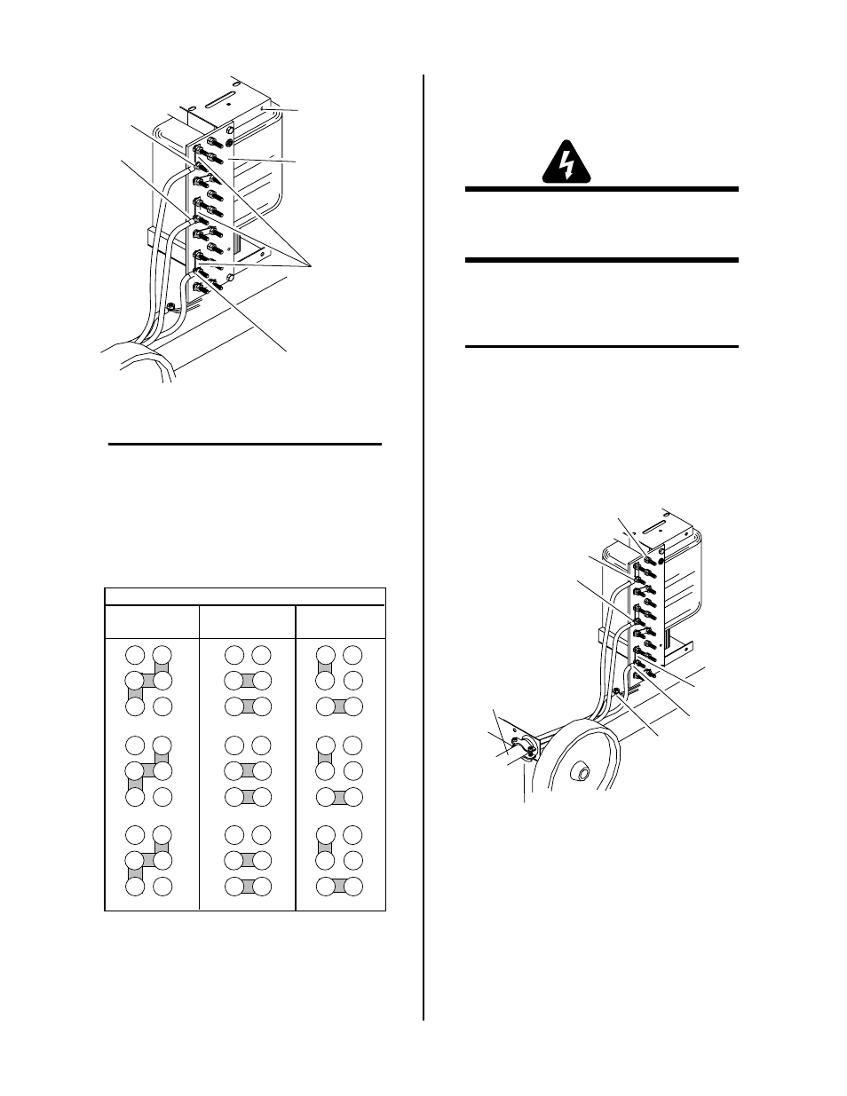
3.07 Primary Power Cable
Connections
WARNING
Disconnect primary power at the source before con-
necting the primary power cable to the power sup-
ply.
The primary power cable must be supplied by the end
user and installed to the Power Supply assembly. Rec-
ommended cable sizes are specified in Appendix 1.
NOTE
Three-phase operation requires a 3-conductor cable
with ground.
1. Route the primary power cable through the strain
relief fitting in the rear panel of the Power Sup-
ply and tighten strain relief screws.
Input Voltage
Terminal Board
L1
L2
L3
Primary Power
Cable
Strain Relief
Fitting
Ground
Connection
Busbars
A-01559
Figure 3-4 Input Voltage Connections
2. Connect the electrical ground wire to the ground
lug on the base of the unit.