Tweco 1000 Merlin(Dec2004) User Manual
Page 35
Manual 0-2708
3-17
INSTALLATION
B. Connecting Torch
WARNING
Disconnect primary power at the source before
disassembling the torch or torch leads.
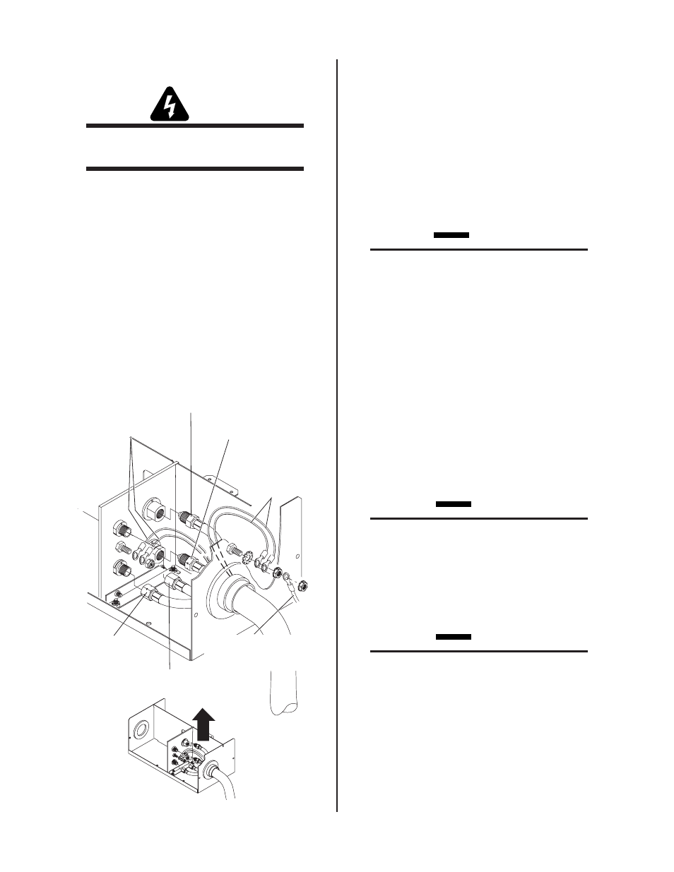
The Torch Leads connect directly to a bulkhead inside the Re-
mote Arc Starter. Connect the Torch Leads as follows:
1. Remove the cover from the Remote Arc Starter if in-
stalled.
2. Remove the hardware attached to the ends of the
Torch Leads assembly with a wire tie.
3. Feed the torch leads through the boot on the torch
end of the Remote Arc Starter.
4. Connect the torch leads connectors to the bulk-
head connections per the following figure.
Outer (GREEN /
YELLOW)
Torch Lead
Shields
External Ground
(Customer Supplied)
Art # A-04002
Torch Leads
Secondary Gas
Plasma Gas (+)
Left-Hand Thread
Coolant Supply (-)
Left-Hand Thread
Coolant
Return
Inner (RED) Torch
Lead Shields
5. Connect the inner shield leads with red wires and ring
terminals to the mounting stud on the bulkhead panel.
6. Remove the nut and bolt mounted to the Remote Arc
Starter front panel. Connect the outer shield leads with
green/yellow wires and ring terminals to the mounting
stud on the inside of the front panel. Secure the stud
to the front panel with a hex nut. Connect a customer-
supplied external ground wire to the stud, outside the
front panel, and secure with a hex nut. Connect the
other end of this ground wire to a properly-installed
earth ground.
CAUTION
If the Arc Starter Box does not include a drilled
hole in the front panel as shown below for the
outer (GREEN / YELLOW) torch lead shields, per-
form the following steps:
• Drill a hole in the area shown.
• Scrape both sides of the front panel down to bare
metal around the hole (to a diameter of ± 3/4" /
19 mm).
• Provide hardware as shown to secure the outer
(GREEN / YELLOW) torch shield leads to the
Arc Starter Box.
• Use the same hardware to connect a customer-
supplied external ground from the Arc Starter
Box to an earth ground.
7. Check the torch for proper parts assembly.
CAUTION
The torch parts (gas distributor, electrode, tip, and
shield cup) must correspond with plasma and sec-
ondary selection, output current level, and type of
operation (cutting or gouging). Refer to Section
4.04, Torch Parts Selection.
8. Check the torch for proper parts assembly.
CAUTION
The torch parts (gas distributor, electrode, tip, and
shield cup) must correspond with plasma and sec-
ondary selection, output current level, and type of
operation (cutting or gouging).
9. Connect the Torch Supply Leads components to the
Remote Arc Starter.