Tweco 1000 Merlin(Dec2004) User Manual
Page 28
INSTALLATION
3-10
Manual 0-2708
4. Feed the connector on the end of the CNC Control
Cable through the rubber boot on the front panel of
the Power Supply (see NOTE).
NOTE
Feed the Control Cable through the rubber boot first
as there will not be enough space inside the rubber
boot for the connector if the Coolant and Gas Leads
have been fed through the rubber boot first.
5. Connect the CNC Control Cable connector to the Con-
trol Cable connector on the Torch Bulkhead Panel.
6. Feed the end of the Torch Leads through the rubber
boot.
7. Refer to the illustration. The Leads Assembly in-
cludes two leads shields; each shield includes two
ring-tongue connectors. Connect the Torch Leads
Shield Wires as follows:
a. Remove one nut and star washer from the torch
leads shield stud on the Torch Bulkhead Panel.
b. Place the ring lugs from the inner (RED) Torch
Leads Shield Wires over the shield stud on the
Torch Bulkhead Panel.
c. Secure the wires with the nut and star washer.
d. Place the ring lugs from the outer (GREEN /
YELLOW) Torch Leads Shield Wires over the
shield stud on the power supply chassis.
e. Use the nut and star washer previously re-
moved from the torch leads assembly to secure
the wires to the shield stud on the power sup-
ply chassis.
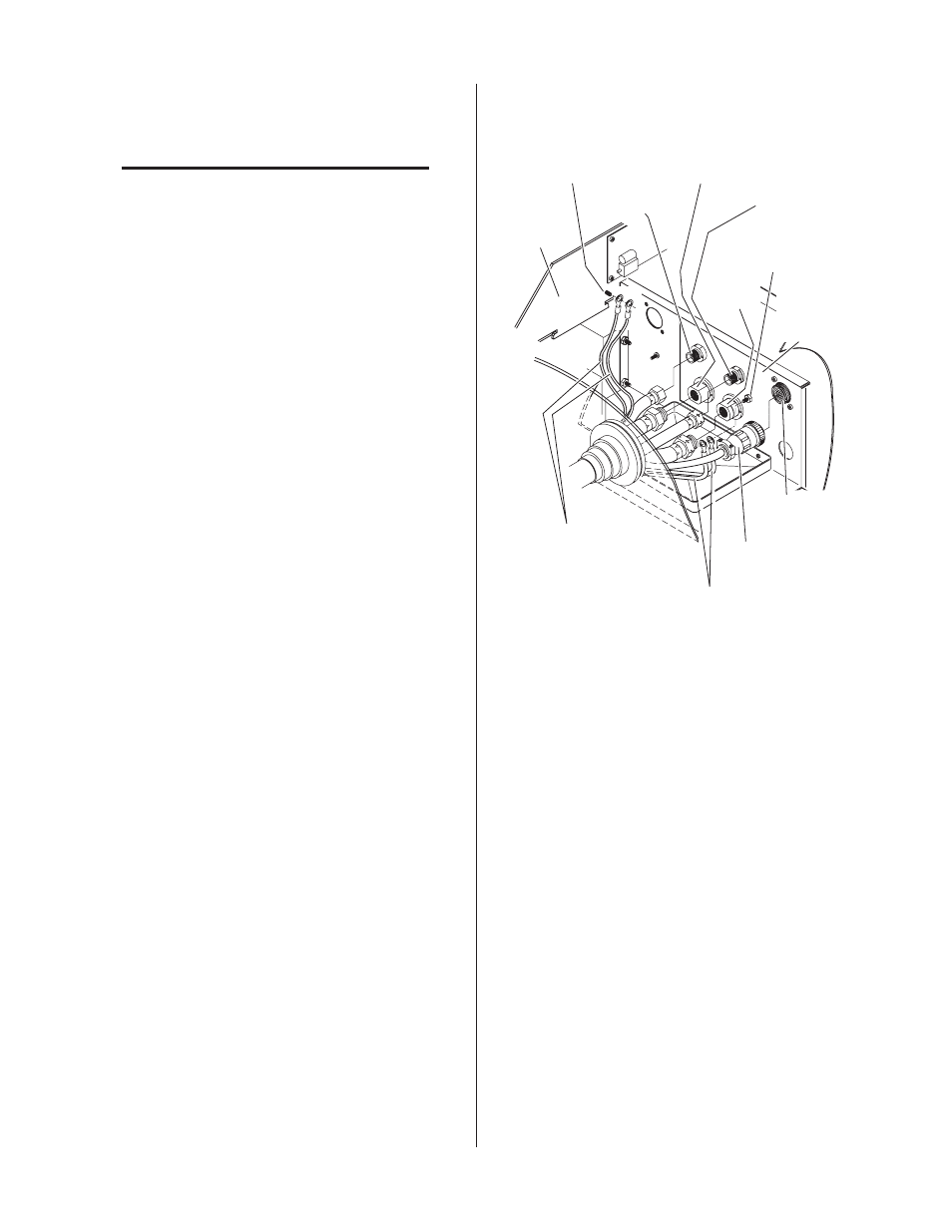
Secondary
Gas
Plasma (+)
Gas
Control Cable
Connector
Coolant
Supply (-)
CNC Control
Cable
RED Shield Wires
With Ring Lugs
Torch Leads
Shield Stud
(for INNER Shields)
GREEN / YELLOW Shield
Wires with Ring Lugs
Torch Leads
Shield Stud
(for OUTER Shields)
Coolant
Return
Art # A-03997
Power
Supply
Chassis
Torch
Bulkhead
Panel
Figure 3-13 Shielded Machine Torch Connections
8. Connect torch coolant and gas leads to connectors
on the Torch Bulkhead Panel.
9. Close the Access Panel and turn the two latching
screws.
10. Check the torch for proper parts assembly.
11. Close the access panel and turn the two latching
screws.