Tweco 1000 Merlin(Dec2004) User Manual
Page 27
Manual 0-2708
3-9
INSTALLATION
c. Connect the air supply hose (see note) to the Air Line
Filter input port (IN) barb fitting and secure with a cus-
tomer supplied hose clamp.
NOTE
The supply hose must be 1/4 inch (6.3 mm) mini-
mum inside diameter to provide adequate air flow.
D. Using Water Secondary
NOTES
Tap water should only be used as a secondary on
machine torches.
The tap water source does not need to be deionized,
but in water systems with extremely high mineral
content a water softener is recommended.
Tap water with high levels of particulate matter
must be filtered.
Tap water can be used instead of a secondary gas and is
connected to the Power Supply as follows:
1. The tap water source must be capable of delivering a
minimum water pressure of 50 - 100 psi (3.5 - 6.9 bar)
and flow of 9 gph (34 lph).
2. Connect the tap water supply hose to the input of a
Water Pressure Regulator.
3. Connect the output of the water regulator to the fitting
marked SECONDARY H2O (water) on the rear panel
of the Power Supply.
A-02164
Water Supply Hose
(Customer Supplied)
WATER
Secondary
Figure 3-11 Secondary Water Connection
3.09 Connecting Torch Leads To
System Without Optional
Remote Arc Starter
NOTE
For Systems using the Optional Remote Arc Starter
refer to Section 3.13 for connecting the Torch.
WARNING
Disconnect primary power at the source before as-
sembling or disassembling the power supply, torch
parts, or torch and leads assembly.
The Torch Leads must be properly installed to the Power
Supply for proper operation. Make all torch connections
to the Torch Bulkhead Panel as follows:
NOTE
Equipment ordered as a system will have the Torch
factory connected to the Power Supply.
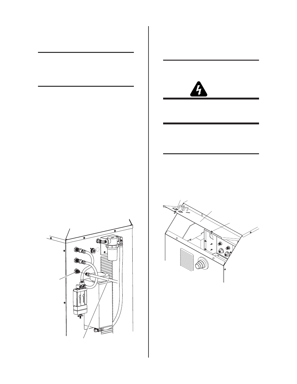
1. Turn the two latch screws securing the Control/Access
Panel to the power supply front panel.
Control/Access Panel
Latch Screw
Latch Screw
A-02165
Figure 3-12 Front Control/Access Panel
Connect the CNC Control Cable and Torch Leads to the Power
Supply as follows:
2. Open the Access Panel to gain access to the Torch
Bulkhead Panel.
3. Remove the hardware attached to the power sup-
ply end of the leads assembly with a tie wrap.