08 ground connections for mechanized applications – Tweco 50 CutMaster User Manual
Page 20
INSTALLATION
3-8
Manual 0-2805
2
3
4
12
14
13
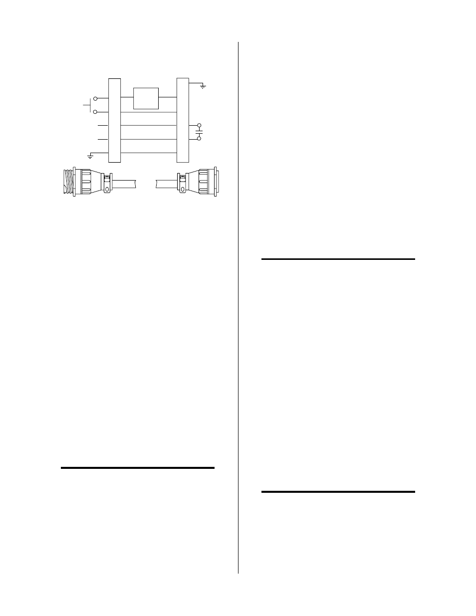
Torch Control
Cable Connector
Remote Pendant/CNC
Cable Connector
PIP
Circuit
Control
OK-To-Move
3
4
12
14
13
A-01366
Remote Pendant Connector Diagram
3.08 Ground Connections For
Mechanized Applications
A. Electromagnetic Interference (EMI)
Pilot arc initiation generates a certain amount of electro-
magnetic interference (EMI), commonly called RF noise.
This RF noise may interfere with other electronic equip-
ment such as CNC controllers, remote controls, height
controllers, etc. To minimize RF interference, follow these
grounding procedures when installing mechanized sys-
tems:
B. Grounding
1. The preferred grounding arrangement is a single point
or “Star” ground. The single point, usually on the
cutting table, is connected with 1/0 AWG (European
50 mm
2
) or larger wire to a good earth ground (refer
to paragraph ‘C’, Creating An Earth Ground). The
ground rod must be placed as close as possible to the
cutting table, ideally less than 10 ft (3.0 m), but no
more than 20 ft (6.1 m).
NOTE
All ground wires should be as short as possible.
Long wires will have increased resistance to RF
frequencies. Smaller diameter wire has increased
resistance to RF frequencies, so using a larger di-
ameter wire is better.
2. Grounding for components mounted on the cutting
table (CNC controllers, height controllers, plasma re-
mote controls, etc.) should follow the manufacturer’s
recommendations for wire size, type, and connection
point locations.
For Thermal Dynamics components it is recom-
mended to use a minimum of 10 AWG (European 6
mm
2
) wire or flat copper braid with cross section equal
to or greater than 10 AWG connected to the cutting
table frame. The connection point must be clean bare
metal; rust and paint make poor connections. For all
components, wires larger than the recommended
minimum can be used and may improve noise pro-
tection.
3. The cutting machine frame is then connected to the
“Star” point using 1/0 AWG (European 50 mm
2
) or
larger wire.
4. The plasma power supply work cable (see NOTE) is
connected to the cutting table at the single point “Star”
ground.
NOTE
Do Not connect the work cable directly to the
ground rod.
5. Make sure work cable and ground cables are prop-
erly connected. The work cable must have a solid
connection to the cutting table. The work and ground
connections must be free from rust, dirt, grease, oil
and paint. If necessary grind or sand down to bare
metal. Use lock washers to keep the connections tight.
Using electrical joint compound to prevent corrosion
is also recommended.
6. The plasma power supply chassis is connected to the
power distribution system ground as required by elec-
trical codes. If the plasma supply is close to the cut-
ting table (see NOTE) a second ground rod is not usu-
ally needed, in fact it could be detrimental as it can
set up ground loop currents that cause interference.
When the plasma power supply is far away from the
ground rod and interference is experienced, it may
help to install a second earth ground rod next to the
plasma power supply. The plasma power supply
chassis would then be connected to this ground rod.
NOTE
It is recommended that the Plasma Power Supply
be within 20 - 30 ft (6.1 – 9.1 m) of the cutting
table, if possible.