Tweco 50 CutMaster User Manual
Page 18
INSTALLATION
3-6
Manual 0-2805
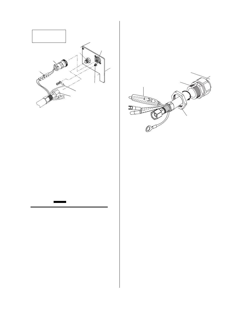
Pilot Lead
Torch Lead
Assembly
Negative/Plasma
Lead
Adapter
Connector
Pilot Lead Stud
Negative/Plasma
Lead Connection
A-03608
Note: Actual Bulkhead
configuration may
differ from that shown.
Adapter
Control Circuit
Connectors
Torch Lead Connections To Bulkhead
6. Connect the Control (PIP) Circuit Connectors to
the mating connectors on the Power Supply
Adapter.
7. Remove the top nut and washer from the Pilot
Stud.
8. Place the lug on the Pilot Control Wire onto the
stud and secure with the nut and washer removed
in Step 7.
9. Tighten the Strain Relief onto the Torch Leads.
10. Check the torch for proper parts assembly.
CAUTION
The torch parts must correspond with the type of
operation. Refer to the appropriate torch manual
for proper parts selection.
11. Re-install the Power Supply Cover on the Power
Supply.
B. Machine Systems (Unshielded Leads)
1. Remove the Cover of the Power Supply to gain
access to the Torch Bulkhead Panel. See Section
5.05.
2. Remove the strain relief nut from the Strain Re-
lief.
Strain Relief
Nut
Strain Relief
Torch Leads
Assembly
A-03609
Remove Tie Wrap,
Remove Insulator,
Disconnect Wires
Strain Relief Nut Removal
3. The Adapter supplied with the Power Supply
must be installed as follows:
a. Inside the Power Supply Bulkhead area, route
the connector on the free end of the Adapter
through the Strain Relief Nut.
b. Continue routing the connector out the hole
in the front of the Power Supply.
c. Feed the end of the torch lead and the Strain
Relief into the hole in the unit while routing
the single black wire into the notch of the Strain
Relief.
d. Tighten the Strain Relief Nut to secure the
Strain Relief to the Power Supply.
4. Connect the torch Negative / Plasma Lead to the
bulkhead connection inside the Power Supply.