07 torch connections – Tweco 50 CutMaster User Manual
Page 17
Manual 0-2805
3-5
INSTALLATION
E. Using High Pressure Gas Cylinders
Refer to the following when using high pressure gas cyl-
inders as the gas supply:
CAUTION
Pressure should be set at 100 psi (6.9 bar) at the
high pressure gas cylinder regulator.
1. Refer to the manufacturer’s specifications for in-
stallation and maintenance procedures for high
pressure gas regulators.
2. Examine the cylinder valves to be sure they are
clean and free of oil, grease or any foreign mate-
rial. Momentarily open each cylinder valve to
blow out any dust which may be present.
3. The cylinder must be equipped with an adjust-
able high-pressure regulator capable of outlet
pressures up to 100 psi (6.9 bar) maximum and
flows of up to 200 scfh (94.3 lpm).
4. Use customer-supplied fitting(s) to connect 1/4"
(6 mm) inside diameter gas supply hose to the
cylinder.
NOTE
Supply hose must be at least 1/4 inch (6 mm) I.D.
For a secure seal, apply thread sealant to the fit-
ting threads, according to manufacturer's instruc-
tions. Do Not use Teflon tape as a thread sealer as
small particles of the tape may break off and block
the small gas passages in the torch.
3.07 Torch Connections
Equipment ordered as a system will have the Torch fac-
tory connected to the Power Supply.
The instructions for connecting the Torch Leads to the
Power Supply are different depending on the type of
leads. This sub-section covers connecting the Torch for
the following applications:
A. Hand Systems
B. Machine Systems (Unshielded Leads)
C. Remote Pendant Control (Optional)
The Torch Leads must be properly installed to the Power
Supply for proper operation. If the torch leads were not
factory-installed, make all torch connections to the Torch
Bulkhead Panel for the desired application.
A. Hand Systems
WARNING
Disconnect primary power at the source before dis-
assembling the torch or torch leads.
1. Remove the Cover of the Power Supply for ac-
cess to the Torch Bulkhead Panel. See Section 5.05.
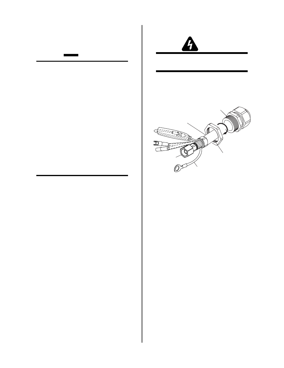
2. Remove the retaining nut from the Strain Relief.
Strain Relief
Nut
Strain Relief
Torch Leads
Assembly
A-03607
Negative /
Plasma Lead
Pilot Lead
Retaining Nut Removal
3. Feed the torch lead ends and the Strain Relief into
the hole in the unit.
4. Secure the Strain Relief with the retaining nut re-
moved earlier.
5. Connect the torch Negative / Plasma Lead to the
bulkhead connection inside the Power Supply.