08 ground connections for mechanized applications – Tweco 50 CutMaster User Manual
Page 19
Manual 0-2805
3-7
INSTALLATION
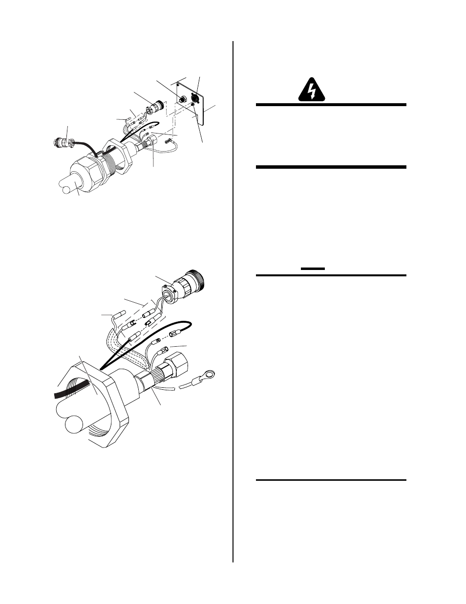
Power Supply Adapter
Pilot Lead
Torch Lead
Assembly
Negative/Plasma
Lead
Negative/Plasma
Lead Connection
A-03610
Control Circuit
Connectors
Remote
Pendant
Adapter
Open
Open
Adapter
Connector
Pilot Lead
Stud
Torch Lead Connections To Bulkhead
A-03611
Pilot Lead
Torch Lead
Assembly
Negative/Plasma
Lead
Control Circuit
Connectors
Open
Open
Power Supply Adapter
Torch Lead Connections To Bulkhead - Detail
5. Connect the Control (PIP) Circuit Connectors to
the mating connectors on the Adapter supplied
on the Power Supply (see Warning).
WARNING
The Adapter supplied with the Power Supply has
two additional Shield Connectors that are used for
Shielded Systems only. These two connectors are
not used and must be taped out of the way to pre-
vent contacting the Negative / Plasma or Pilot
Leads.
6. Remove the top nut and washer from the Pilot
Stud.
7. Place the lug on the Pilot Control Wire onto the
stud and secure with the nut and washer removed
in the above Step.
8. Tighten the Strain Relief onto the Torch Leads.
9. Check the torch for proper parts assembly per the
torch manual.
CAUTION
The torch parts must correspond with the type of
operation. Refer to Section 4.04-A, Torch Parts
Selection.
10. Reinstall the Power Supply Cover on the Power
Supply.
C. Remote Pendant Control (Optional)
In machine type operations the Power Supply has an
Adapter that has a cable connector supplied at each
end of the Adapter. One end is connected at the fac-
tory to the mating connector on the Power Supply
Bulkhead area. The other end allows connection of a
Remote Pendant. The remote pendant lead connec-
tor allows connection to a remote pendant or CNC
cable while using Control (PIP) Circuit connections
in the Torch Assembly.
Connect the remote pendant control cable to the con-
nector provided on the Adapter from the Power Sup-
ply.
NOTE
Refer to Appendix 3, Torch Control Cable Wiring
Diagram For Mechanized Systems, for detailed
schematic of the Adapter.