05 input power connections, 06 checking input connections – Tweco Merlin 6000 Plasma Cutting CE Slave Power Supply User Manual
Page 18
INSTALLATION PROCEDURES
3-2
Manual 0-2603
3.05 Input Power Connections
The Power Supply accepts input voltages of 380/415V,
50 or 60 Hz, three-phase power.
A. Electrical Connections
The power source must conform to local electric code and
the recommended circuit protection and wiring require-
ments shown in Appendix 1.
B. Opening Power Supply Enclosure
The left side panel (viewed from the front) of the Power
Supply must be removed to make electrical connections
and to select the proper input voltage.
WARNING
Disconnect primary power at the source before as-
sembling or disassembling power supply, torch
parts, or torch and leads assemblies.
1. Remove the ten screws which secure the left side
panel (viewed from the front) to the Power Sup-
ply.
Left Side Panel
Screws
(10 Places)
A-01528
Figure 3-2 Opening Power Supply
2. Remove the left side panel from the Power Sup-
ply.
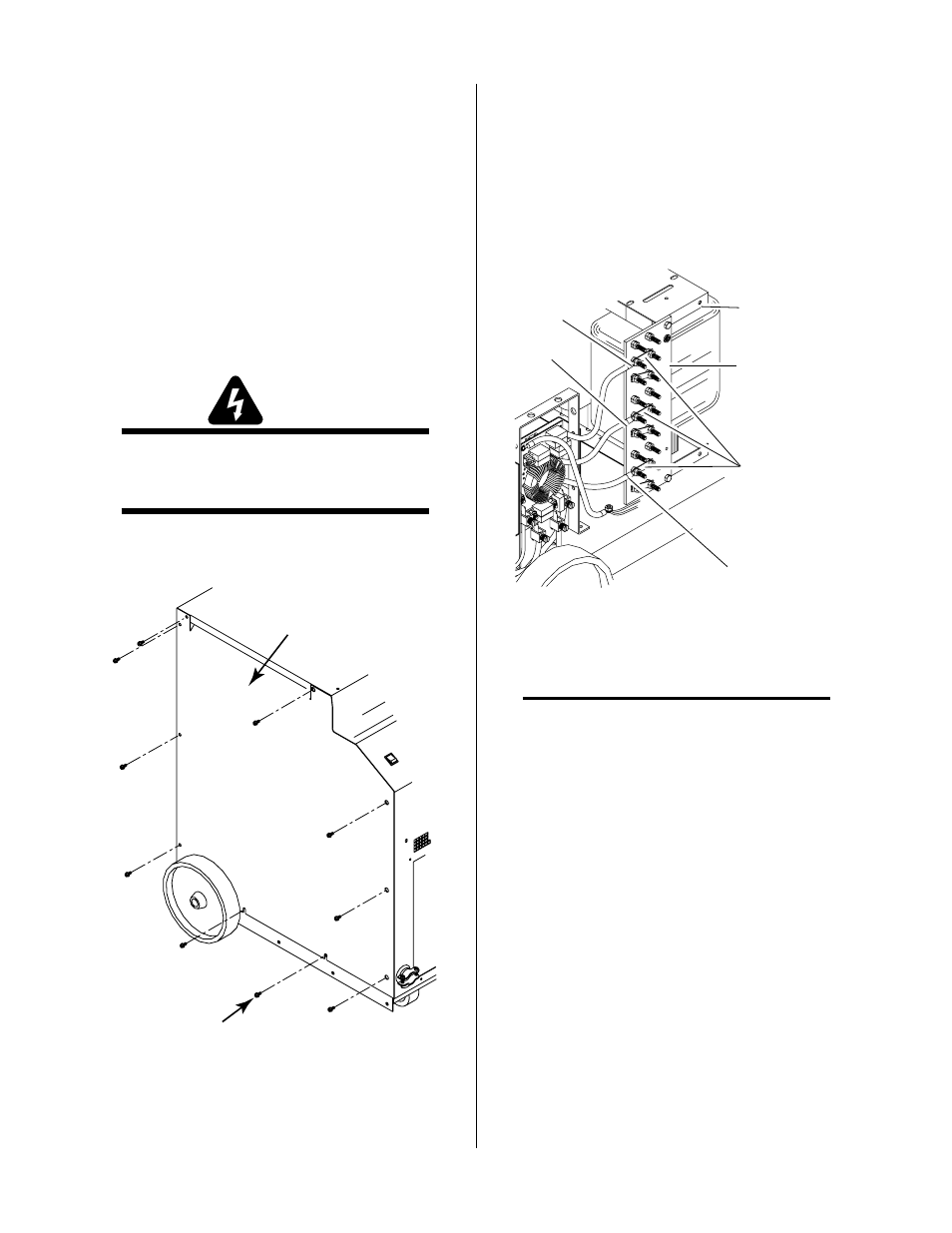
3.06 Checking Input Connections
The Power Supply is wired to use input voltages of 380/
415 VAC. Internal busbars must be checked on the input
voltage terminal board to verify proper installation.
1. Locate the input voltage terminal board on the
left side of the power supply.
Input Voltage
Terminal Board
L1
L2
L3
Busbars
A-01091
Extra Busbar
Storage Location
Figure 3-3 Input Voltage Terminal Board Location
NOTE
Extra busbars are attached (stored) to the top side
of the power transformer assembly.
2. Check the busbar configuration on the input volt-
age terminal board . The busbar configuration
must correspond with the available line voltage
per the following figure and the label inside the
unit: