03 specifications & design features, 04 theory of operation – Tweco Merlin 6000 Plasma Cutting CE Slave Power Supply User Manual
Page 16
INTRODUCTION & DESCRIPTION
2-2
Manual 0-2603
2.03 Specifications & Design
Features
The following apply to the Slave Power Supply only:
1. Controls
ON/OFF Switch
2. Control Indicators
AC , TEMP, DC LED Indicators
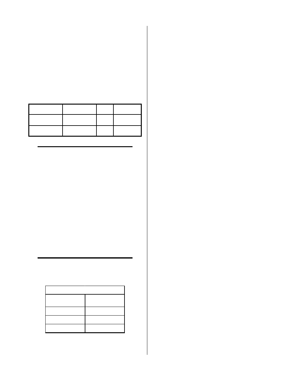
3. Input Power
V o lt a g e
F re q u e n cy
P h a se A m p e ra g e
3 8 0
5 0 o r 6 0 H z
3
5 1
4 1 5
5 0 o r 6 0 H z
3
4 7
NOTE
Refer to Appendix 1 for recommended input wir-
ing size, current ratings, and circuit protection re-
quirements.
Amperage depends on input voltage (Refer to Ap-
pendix 1).
4. Output Power
Slave Power Supply:
50 to 150 amps
Total output of Master/Slave Power Supplies:
Continuously adjustable by potentiometer from
100 to 300 amps (Minimum of 50 amps if Slave
Power Supply is Turned OFF)
5. Duty Cycle (see NOTE)
NOTE
The duty cycle will be reduced if the primary in-
put voltage (AC) is low or the DC voltage is higher
than shown in the chart.
Ambient
Temperature
104° F (40° C)
Duty Cycle
100%
Current
150 Amps
DC Voltage
140 vdc
Power Supply Duty Cycle
6. Power Supply Dimensions
Enclosure Only -
Width: 24.12 in (0.61 m)
Height: 38.38 in (0.98 m)
Depth: 34.25 in (0.87 m)
Fully Assembled -
Width: 28.50 in (0.72 m)
Height: 43.38 in (1.10 m)
Depth: 43.75 in (1.11 m)
7. Weight of Power Supply Only
575 lbs (260.8 kg)
2.04 Theory Of Operation
A. Input and Output Power
The Power Supply accepts input voltages of 380/415V,
50 or 60 Hz, three-phase. The unit converts AC input
power to DC power for the main cutting arc. The nega-
tive output is connected to the torch electrode through
the negative torch lead, and the positive output connects
to the workpiece through the work cable.
B. Main Cutting Arc
The Power Supply accepts 50 or 60 Hz three-phase line
input. The power supply converts AC input power to
DC power for the main cutting arc. The negative output
is connected to the torch electrode through the negative
torch lead. The positive output is connected to the work-
piece via the work cable and clamp connection.
C. Thermal Interlocks
The system has built-in thermal interlocks to provide safe
and efficient operation. When an interlock shuts down
the system, the torch switch (or control device) must be
used to restart the system.
Thermal overload sensors are located in the transformer
and main heatsink in the power supply. If one of these
components is overheated the appropriate switch will
open up, causing the temperature light to turn from green
to red and shutting off power to the main contactor. When
the overheated component cools down the switch will
close again and allow operation of the system.