Section 3: installation procedures, 01 introduction, 02 site location – Tweco Merlin 6000 Plasma Cutting CE Slave Power Supply User Manual
Page 17: 03 unpacking, 04 removing skid, Section 3, Installation procedures -1
Manual 0-2603
3-1
INSTALLATION PROCEDURES
SECTION 3:
INSTALLATION
PROCEDURES
3.01 Introduction
This Section describes installation of the Slave Power
Supply. These instructions apply to the Slave Power Sup-
ply Assemblies only; installation procedures for Master
Power Supply, Options and Accessories are given in
Manuals specifically provided for those units.
The complete installation consists of:
1. Site selection
2. Unpacking
3. Connections to Power Supply
a. Input power
b. Internal power selection
c. Work cable
d. Parallel Cable connection
e. Pilot and Power Lead Connections
4. Grounding
5. Operator training
3.02 Site Location
Select a clean, dry location with good ventilation and ad-
equate working space around all components.
CAUTION
Operation without proper air flow will inhibit
proper cooling and reduce duty cycle.
The Slave Power Supply is cooled by air flow through
the front, rear, and side panels. Air flow must not be ob-
structed. At least 2 feet (0.61 m) of clearance should be
provided on all sides.
NOTE
When using the Slave Power Supply in parrallel
with the Master Power Supply the supplies should
be placed next to each other. Placing one Power
Supply behind the other will cause heated air to be
drawn into the rear Power Supply. This condition
may lower the duty cycle of the system.
Review the safety precautions in the front of this manual
to be sure that the location meets all safety requirements.
3.03 Unpacking
A. Slave Power Supply
The power supply is skid-mounted and protected with a
carton and padding material to prevent damage during
shipment. The power supply, work cable are factory-as-
sembled and packaged together.
B. Unpacking Procedure
1. Unpack each item and remove all packing mate-
rial.
2. Locate the packing list(s) and use the list to iden-
tify and account for each item.
3. Inspect each item for possible shipping damage.
If damage is evident, contact your distributor be-
fore proceeding with installation.
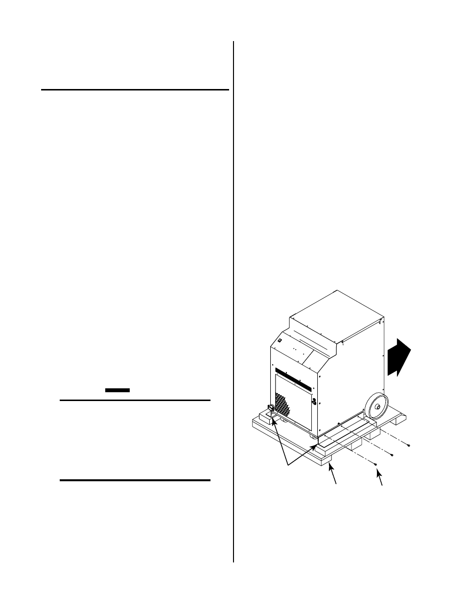
3.04 Removing Skid
The Power Supply is mounted on the skid with two brack-
ets. Remove the Power Supply from the skid per the fol-
lowing procedure:
1. Remove the six bolts connecting the brackets to the
base of the Power Supply.
A-01527
Three Bolts
(Each Side)
Shipping Brackets
Shipping Pallet
Figure 3-1 Skid Removal From Power Supply
2. Roll the Power Supply off the skid backwards (rear
wheels first).