Trebor SL20 CHAMPION User Manual
Page 11
CHAMPION SL20 PUMP OPERATION / MAINTENANCE MANUAL
PAGE 11
3.1.f Booster
Mode
In booster mode the controller disables the vacuum generators. Booster mode
can be used in both auto and manual tune modes to take in a low pressure
source and increase the pressure to the desired outlet pressure.
Booster mode is enabled by setting the PLC internal relay 17904 to “on.”
This feature is useful when the pump has a positive fluid inlet pressure greater
than 5 psig to reduce air consumption improving pump efficiency.
3.1.g Preventative Maintenance (PM) Counter
The PLC has a preventative maintenance counter that counts cycles since the
last maintenance was done on the pump. In addition, the pump has a user
adjustable limit for the PM count. When the limit has been reached the display of
the PLC will display the message “User 1.” Pressing any button on the PLC will
clear this message.
The PM counter occupies two registers. The lower register counts to 10,000
then increments the upper register. Thus the PM counter’s value can be
calculated by multiplying the upper register by 10,000 and then adding the lower
register.
The PM counter limit also occupies two registers. The PM limit registers are set
up the same way as the PM counter registers.
For example, to set the PM counter limit to 10,000,000 the PM limit high register
would be set to 1000 and the PM limit lower register would be set to 0.
To reset the PM counter after doing maintenance on the pump, set the PLC
internal relay 17905 to “on” thus toggling the relay. It will immediately return to
“OFF” after resetting the PM counter.
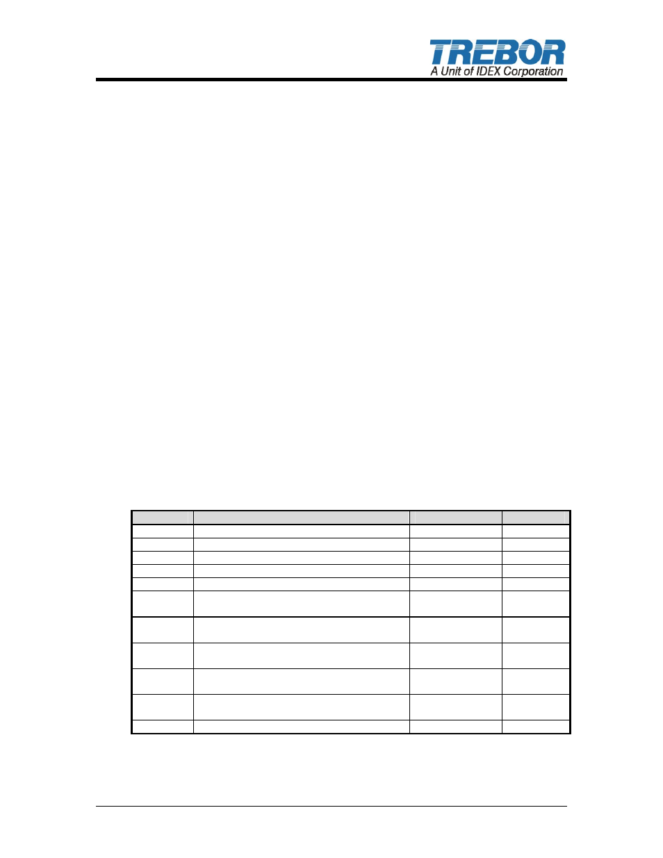
3.1.h Changing PLC data stores listed in table 3:
DM
Description
Range
Actions
0
Cycle Rate – in cycles per minute
5 – 70
Read Only
1
Overlap – in milliseconds (400 Default)
0 – 500
Read/Write
2
Fill Time – in milliseconds (500 Default)
50 – 5000
Read/Write
3
Stroke Time – milliseconds (900 Default)
500 – 6000
Read/Write
4
Seat Time – in milliseconds
NA – calculated
Read Only
5
Fill Error - difference between fill time of
each head as percentage
0 – 100
Read Only
6
PM Counter High – high order digits of PM
count
0 – 65535
Read Only
7
PM Counter Low – low order digits of PM
count
0 – 10000
Read Only
8
PM Limit High – high order digits of PM
count limit
0 – 65535
Read/Write
9
PM Limit Low – low order digits of PM
count limit
0 – 10000
Read/Write
10
Auto Tune Delay – in seconds
0 – 60
Read/Write
Table 22: PLC Data Memories
• Push
the
⇔ button repeatedly until “DM” (data memories) is displayed in the
“selected device type” area of the PLC display.