Wiring examples, Thermostat 507 – tekmar 507 Thermostat Installation User Manual
Page 4
© 2010
D 507 - 05/10
4 of 8
Pivot front
cover around
bottom hinges
Align hinges
on bottom
of front cover
1
2
Menu
Item
STEP FIVE
WIRING THE THERMOSTAT
(Refer to the examples on the following page.)
24 V (ac) Power
Connect the 24 V (ac) power to the R and C terminals of the thermostat. This connection
provides power to the microprocessor and display of the thermostat.
Heat Relay (Rh - W)
The Heat Relay Rh - W terminals are an isolated output. There is no power available
on these terminals from the thermostat. These terminals are to be used as a switch for
a 24 V (ac) circuit. This circuit can operate a low current 24 V (ac) device directly or an
external relay to enable a line voltage or high current device.
STEP SIX
INSTALLING THE FRONT COVER
Align the hinges on the bottom of
the front cover with the bottom of the
thermostat mounting base. Pivot the
front cover around the bottom hinges
and push the top against the mounting
base until it snaps firmly in place.
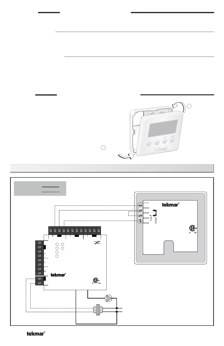
Wiring Examples
N
115 V (ac)
24 V (ac)
Class 2
Transformer
L
Meets Class B:
Canadian ICES
FCC Part 15
Made in
Canada
Apr 2010
Lot 1234
24 V ±10% 50/60 Hz 1.6 VA.
24 V (ac) 2 A Class 2
Power:
Relay:
954-01
Thermostat 507
One Stage Heat
507
For 3 wires,
install jumper
R to Rh
2
1
CR
Rh
W
34
24 V
Power
Zone 1
Zone 2
Zone 3
Zone 4
End Switch
C
Zone 2
W
tN4
R
C
Zone 3
W
tN4
R
C
Zone 4
W
tN4
R
tN4 Wiring Center 316
Four Zone Pumps
W
tN4
C
tN4
C
Zone 1
E
xpansion
End Switch
C
Input P
ow
er
R
R
H8002A
X
X
Input Power:
24 V (ac) ±10% 60 Hz
11 VA Class 2
End Switch:
24 V (ac) 2 A
Pump Relays: 115 V (ac) 5 A
Zone Power:
115 V (ac) 12 A
Made in Canada
tektra 1031-01
Use at least 167°F (75°C) conductors
Black
Re
d
115 V (ac)
24 V (ac)
Wiring to a tekmar Wiring Center 315 or 316