Installation – tekmar 507 Thermostat Installation User Manual
Page 3
3 of 8
© 2010
D 507 - 05/10
Installation
STEP ONE
GETTING READY
Check the contents of this package. If any of the contents are missing or damaged, please
contact your wholesaler or tekmar sales representative for assistance.
Type 507 Includes: •• One Thermostat 507 •• Data Brochure D 507 • User Brochure U 507
STEP TWO
REMOVING THE FRONT COVER
Menu
Item
Remove cover
Push tab
1
2
Place a screwdriver or similar object into the small
slot located in the top of the thermostat. Push the
screwdriver against the plastic tab and pull the top of
the front cover so that it pivots around the bottom edge
of the base.
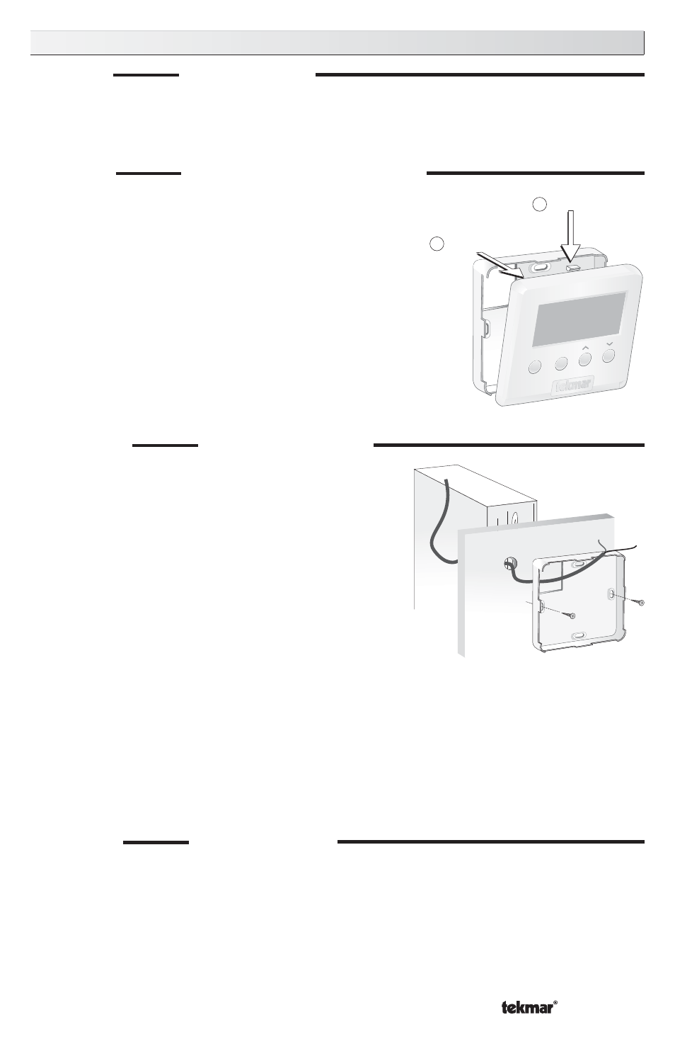
STEP THREE
MOUNTING THE BASE
The thermostat should be installed on an interior wall
of the desired zone approximately 5’ (1.5 m) above
the floor. Do not mount the thermostat in a location
that may be affected by localized heat sources or
cold drafts. It may be necessary to install a draft
barrier behind the thermostat to prevent air from
blowing through the wiring hole and affecting the
thermostat’s built-in sensor.
Mount the base directly to the wall using two #6
1” screws. The screws are inserted through the
mounting holes and must be securely fastened
to the wall. If possible, at least one of the screws
should enter a wall stud or similar surface. If the
thermostat is to be mounted to a 2” x 4” electrical
box, order an Adaptor Plate 007. This plate mounts
to the electrical box and the thermostat mounts to
the plate. Ensure that the electrical box does not
provide cold air to the thermostat.
#6 1” screws
STEP FOUR
ROUGH IN WIRING
• 18 AWG or similar wire is recommended for all 24 V (ac) wiring.
• All wires are to be stripped to 1/4” (6 mm) to ensure proper connection to the control.
• Run wires from the 24 V (ac) power to the thermostat. Use a clean power source to
ensure proper operation.
• Run wires from the heating device to the thermostat.