Sizing the transformer control wiring – tekmar 403 House Control Installation User Manual
Page 4
© 2011
D 403 - 07/11
4 of 32
DHW Pump
Power
Source 1
Variable
Speed Pump
Boil System
Pump
The control requires an external transformer with 20 VA
capacity or greater. A tekmar Transformer 009 (or 009K
which includes a 4” x 4” electrical box) can supply up to 40
VA, and includes an in-line fuse to protect the transformer
and control.
Sizing the Transformer
Control Wiring
Line Voltage Wiring-----------------------------------------------------------------------------------
-----------------------------------------------------------------------------------
Ensure Junction Box Extension Ring is Installed
An extension ring must be installed on the 4” x 4”
junction box when 6 or more powered outputs for the
pumps are used on the rear of the control.
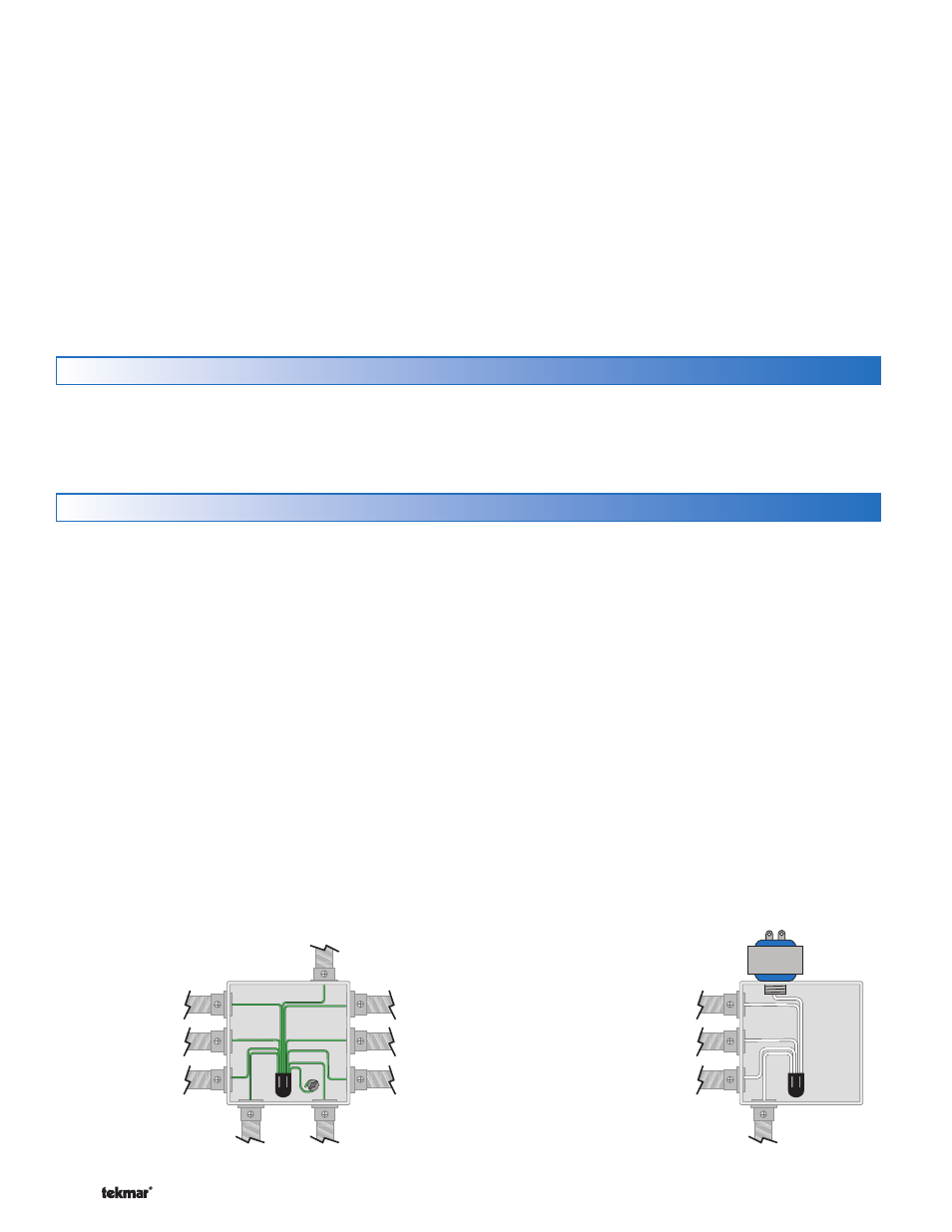
Ground the Pumps
Connect the pump grounds to the power supply
ground as shown in Figure 1. The ground wire must
also be grounded to the electrical box.
Wire the Pump Neutrals
If the combined pump power load is less than 12 A,
then a only a single 15 A circuit is required.
If the combined pump power load exceeds 12 A, then
two separate 15 A circuits are required.
Each power circuit requires it’s own neutral wire.
Connect the Neutral (N) wires from each pump and wire
to the 115 V (ac) Neutral (N) wire. If the transformer has
•
•
•
•
•
•
been mounted to this electrical box, connect its neutral
wire with this group. This is shown in Figure 2 and 3.
Wire the Pump Power (L)
If the combined pump power load is less than 12 A,
then a only a single 15 A circuit is required.
If the combined pump power load exceeds 12 A, then
two separate 15 A circuits are required.
Connect the 115 V (ac) line voltage (L) wire to the red
Pump Power (L) wire on the back of the House Control
and to the 115 V (ac) side of the transformer. Use a
wire nut or approved connector. See Figure 4.
Wire the Pumps
Wire each remaining line voltage pump wire into the
push-in wire connector of the corresponding pump
lead on the back of the House Control. This is shown
in Figure 5 and 6.
•
•
•
•
CAUTION: TURN ALL POWER OFF BEFORE PERFORMING ANY WIRING.
DHW Pump
Power
Source 1
Power
Source 2
Zone 4 Pump
Zone 3 Pump
Zone 2 Pump
Zone 1 Pump
Variable
Speed Pump
Boil System
Pump
Figure 1 - Connect
Ground Wires
Figure 2 - Connect Neutral Wires
for Power Source 1
Each cable must be pulled from the equipment to the
control’s plastic enclosure. All low voltage wiring connections
enter the enclosure through conduit knockouts on the
sides, or through the square knockouts on the rear. It is
recommended to label each cable for easy identification.
All low voltage wires are to be stripped to a length of 3/8”
(9 mm) to ensure proper connection to the control.
Pull two conductor 18 AWG LVT cable, up to 500 feet
(150 m) for the following equipment:
tekmarNet
®
2 Thermostats
Mixing Valve Actuator Proportional 0-10 V (dc)
Boiler Stage 1 T-T
Boiler Stage 2 T-T (if applicable)
•
•
•
•
Modulating Boiler 0-10 V (dc) or 4-20 mA (if applicable)
Outdoor Temperature Sensor
Boiler Supply Temperature Sensor
Mix Supply Temperature Sensor
DHW Tank Temperature Sensor (if applicable)
DHW Tank Aquastat (if applicable)
Setpoint Device (if applicable)
Pull three conductor 18 AWG LVT cable for the following
equipment:
Mixing Valve Actuator Floating Action
tekmarNet
®
4 Accessories (User Switch, Timer)
•
•
•
•
•
•
•
•
•
Low Voltage Wiring -----------------------------------------------------------------------------------
-----------------------------------------------------------------------------------