tekmar 370 House Control User Manual
Page 7
Copyright © D 370 -06/99
7 of 20
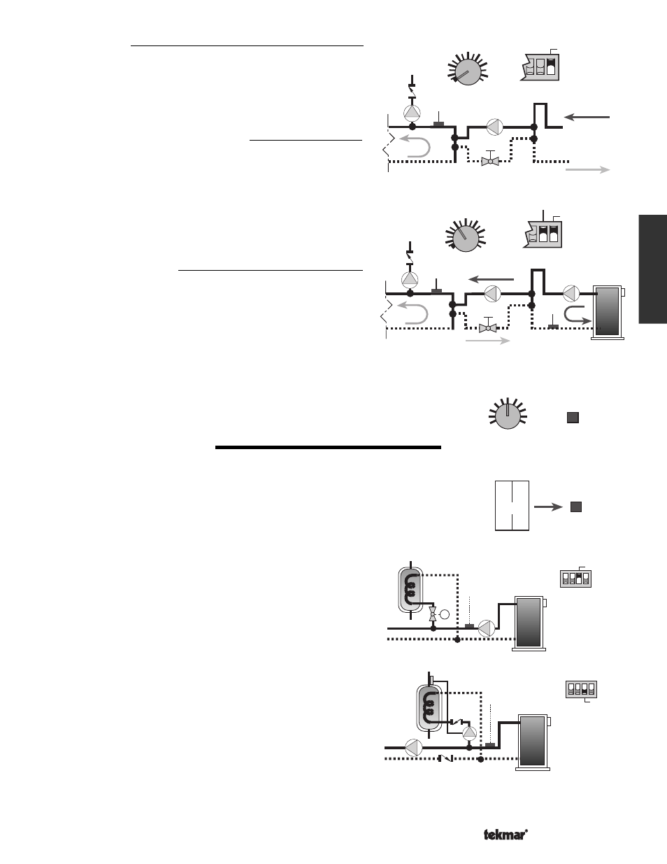
Boiler Enable
If no Boiler Sensor is installed and the
Min. Boiler Supply dial is set to
the
Off position, the Boiler relay can be used to provide a heat demand
to an external multiple boiler staging control. In order to prevent short
cycling the 370 turns on the
Boiler relay when the variable speed
output is between 10% and 25%. The
Boiler relay then has a minimum
on time of 3 minutes and a minimum off time of 20 seconds.
Boiler Enable With Boiler Protection
Only when the boiler supply water temperature is measured by a boiler
return sensor, can the 370 provide direct boiler protection. The DIP
switch must be set to
Boiler Return. The aquastat in the boiler should
be set to Boiler Outdoor design water temperature. When the boiler is
fired and the boiler return temperature is near (or below) the
Min. Boiler
Supply dial setting, the 370 turns on the Minimum Boiler light and
reduces the heating load on the boiler. During this warm up period, the
injection pump is run at a slower speed and some of the zones may be
prevented from operating.
Boiler Load Reduction
When the
Boiler relay is turned on after a period of no operation, the
370 only allows one zone to operate until the boiler supply water
temperature reaches the
Min. Boiler Supply setting and the system
supply water temperature approaches the target supply temperature.
This helps the boiler to warm up as fast as possible. Once the target
system supply water temperature is reached, the other zones are
allowed to operate.
Maximum System Supply
The 370 has a
Max. System Supply dial that can be used to set an upper limit to the system
supply water temperature. If the supply water temperature approaches the
Max. System
Supply dial setting, the 370 turns on the Maximum Supply light and reduces the speed
of the injection pump.
DOMESTIC HOT WATER (DHW)
The DHW tank requests heat from the 370 through a DHW Demand. Whenever 24 V (ac)
or 120 V (ac) is applied to the
DHW Dem — DHW Dem (22 and 23) terminals on the 370,
the control registers a DHW Demand and turns on the
DHW Demand light. An aquastat,
setpoint control or other switching device can be used to generate a DHW Demand by wiring
the voltage signal through the switching device and into the
DHW Dem — DHW Dem
terminals.
DHW Valve / DHW Pump
Once the 370 has received a DHW Demand, the sequence of opera-
tion is dependent on the position of the
DHW Valve / DHW Pump
DIP switch.
DHW Valve (Boiler Operation)
If the DIP switch is set to
DHW Valve, the system pump is turned on
and the DHW valve is opened through the
DHW Pmp / Vlv relay. The
370 assumes a fast acting zone valve is used and the
Thermal Motor
DIP switch has no effect on the operation of the
DHW Pump/ Vlv relay.
DHW Valve (Mixing Operation)
If the DIP switch is set to
DHW Valve, the DHW valve is opened
through the
DHW Pmp / Vlv relay. The boiler loop pump must be
turned on through an external relay that is operated by the DHW valve
end switch.
DHW Pump (Boiler or Mixing Operation)
If the DIP switch is set to
DHW Pump, the 370 turns on the DHW
Pump through the
DHW Pmp / Vlv relay. Operation of the system
and boiler pump is not required (See application A 370-5).
DHW Supply Temperature
During the DHW operation, the 370 targets a boiler water temperature of at least 180
°F (82°C).
Max. System
Supply
120
170
°F
220
Maximum
Supply
22 23
DemDem
DHW
DHW
Demand
P
M
DHW Valve
P
DHW Pump
Supply
Sensor
130
°F
Off
165
Min. Boiler
Supply
100
From Heat Source
To Heat Source
Mixing
Operation
Boil
Sensor
Supply
Sensor
130
°F
Off
165
Min. Boiler
Supply
100
Mixing
Boiler Return