tekmar 370 House Control User Manual
Page 13
Copyright © D 370 -06/99
13 of 20
Room Temperature Units (RTU) and Indoor Sensors
RTUs and / or Indoor Sensors provide indoor temperature feedback to the control.
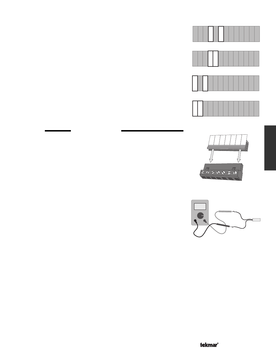
DIP Switch set to Zone 1 Heating
• If zone 4 is used, connect an RTU 054 or Indoor Sensor 076 to the
Com Sen —
RTU 4 (8 and 10) terminals on the control.
• If zone 3 is used, connect an RTU 054 or Indoor Sensor 076 to the
Com Sen —
RTU 3 (8 and 9) terminals on the control.
• If zone 2 is used, connect an RTU 054 or Indoor Sensor 076 to the
Com Sen —
RTU 2 (5 and 7) terminals on the control.
• If the zone 1 is used for heating, an RTU 054 or Indoor Sensor 076 must be
connected to the
Com Sen — RTU 1 (5 and 6) terminals on the control.
DIP Switch set to Zone 1 Cooling
• If the zone
1 relay is used to enable an external cooling control system, an RTU or
Indoor Sensor is not required for this zone.
• If the zone
1 relay is used to control a cooling unit, an RTU 054 or Indoor Sensor
076 must be connected to the
Com Sen — RTU 1 (5 and 6) terminals on the control.
STEP FIVE
TESTING THE WIRING
Each terminal block must be unplugged from its header on the control before power
is applied for testing. Pull straight down to unplug the terminal block.
The following tests are to be performed using standard testing practices and procedures and
should only be carried out by properly trained and experienced persons.
A good quality electrical test meter, capable of reading from at least 0 — 200 V (ac) and at
least 0 — 2,000,000 Ohms, is essential to properly test the wiring and sensors.
Test the Sensors
−−−−−−−−−−−−−−−−−−−−−−−−−−−−−−−−−−−−−−−−−−−−−−−−
−−−−−−−−−−−−−−−−−−−−−−−−−−−−−−−−−−−−−−−−−−−−−−−−
−−−−−−−−−−−−−−−−−−−−−−−−−−−−−−−−−−−−−−−−−−−−−−−−
−−−−−−−−−−−−−−−−−−−−−−−−−−−−−−−−−−−−−−−−−−−−−−−−
−−−−−−−−−−−−−−−−−−−−−−−−−−−−−−−−−−−−−−−−−−−−−−−−
In order to test the sensors and Room Temperature Units (RTUs), the actual temperature
at each sensor and RTU location must be measured. A good quality digital thermometer
with a surface temperature probe is recommended for ease of use and accuracy of testing.
Where a digital thermometer is not available, a spare sensor can be strapped alongside
the one to be tested and the readings compared. Test the sensors and RTU(s) according
to the instructions in the Data Brochures D 070 and D 054.
Test the Power Supply
Make sure exposed wires or bare terminals are not in contact with other wires or grounded
surfaces. Turn on the power and measure the voltage between the
Power N — L (2 and 3)
terminals using an AC voltmeter, the reading should be between 110 and 130 V (ac).
Test the Powered Inputs
If a DHW Demand is used, measure the voltage between terminals
DHW Dem — DHW Dem (22 and 23). When the DHW Demand
device (aquastat etc.) calls for heat, you should measure between 22 and 130 V (ac) at the terminals. When the DHW Demand device
is off, you should measure less than 5 V (ac).
Test the Outputs
System Pump
If a system pump is connected to the
Sys Pmp (1) terminal, make sure power to the terminal block is off and install a jumper between
the terminals
Sys Pmp — Power L (1 and 3). When power is applied to the terminals Power N — L (2 and 3), the system pump should
start. If the pump does not turn on, check the wiring between the terminal block and the pump and refer to any installation or
troubleshooting information supplied with the pump. If the pump operates properly, disconnect the power and remove the jumper.
Variable Speed Injection Pump
If a variable speed injection pump is connected to the terminal
Var. Pmp (4), make sure power to the terminal block is off and install
a jumper between the terminals
Power L — Var . Pmp (3 and 4). When power is applied to terminals Power N — L (2 and 3), the
variable speed injection pump should operate at full speed. If the pump does not operate, check the wiring between the terminal
block and the pump and refer to any installation or troubleshooting information supplied with the pump. If the pump operates properly,
disconnect the power and remove the jumper.
Com
Sen
UnO
Sw
RTU
2
8
RTU
3
5 6
7
RTU
4
RTU
1
Com
Sen
9 10
12
Zo
In
11
13
Com
Sen
Sup
Sen
Com
Sen
14
16
Out
Sen
15
17
Boil
Sen
Com
Sen
UnO
Sw
5 6
RTU
1
12
Zo
In
11
13
Com
Sen
Sup
Sen
Com
Sen
14
16
Out
Sen
15
17
Boil
Sen
RTU
2
7
RTU
3
9
RTU
4
10
8
Com
Sen
Com
Sen
UnO
Sw
5 6
RTU
4
RTU
1
10
12
Zo
In
11
13
Com
Sen
Sup
Sen
Com
Sen
14
16
Out
Sen
15
17
Boil
Sen
RTU
2
7
8
RTU
3
Com
Sen
9
Com
Sen
UnO
Sw
8
RTU
3
5
6
RTU
4
RTU
1
Com
Sen
9 10
12
Zo
In
11
13
Com
Sen
Sup
Sen
Com
Sen
14
16
Out
Sen
15
17
Boil
Sen
RTU
2
7
11 12 13
15
14
16 17
Boil
Sen
Zo
In
Out
Sen
Com
Sen
UnO
Sw
Com
Sen
Sup
Sen
Ω
Ω
Installation