tekmar 370 House Control User Manual
Page 11
Copyright © D 370 -06/99
11 of 20
STEP THREE
ROUGH-IN WIRING
All electrical wiring terminates in the control base wiring chamber. The base has standard 7/8" (22 mm) knockouts which accept common
wiring hardware and conduit fittings. Before removing the knockouts, check the wiring diagram and select those sections of the chamber
with common voltages. Do not allow the wiring to cross between sections as the wires will interfere with safety dividers which should
be installed at a later time.
Power must not be applied to any of the wires during the rough-in wiring stage.
• Install the Outdoor Sensor 070 and Boiler Sensor 071 according to the instructions in the Data Brochure D 070 and run the wiring
back to the control. If the 370 is used as a mixing control, a Supply Sensor 071 is required. Install the Supply Sensor according to
the instructions provided in the Data Brochure 070 and run the wiring back to the control.
• If an Indoor Sensor 076 is used, install the Indoor Sensor(s) according to the installation instructions in the Data Brochure 070 and
run the wiring back to the control.
• If an RTU 054 is used, install the RTU(s) according to the installation instructions provided in the Data Brochure D 054 and run the
wiring back to the control.
• If a Zone Control is used, run the wires from the Zone Control to the 370. Refer to the instructions supplied with the Zone Control.
• Run wiring from the other system components (pumps, boiler, motorized zone valves, etc.) to the control.
• Run wires from the 120 V (ac) power to the control.
Use a clean power source to ensure proper operation.
• Multi-strand 16 AWG wire is recommended for all 120 V (ac) wiring due to its superior flexibility and ease of installation into
the terminals.
STEP FOUR
ELECTRICAL CONNECTIONS TO THE CONTROL
The installer should test to confirm that no voltage is present at any of the wires. Push the control into the base and slide it down until
it snaps in firmly.
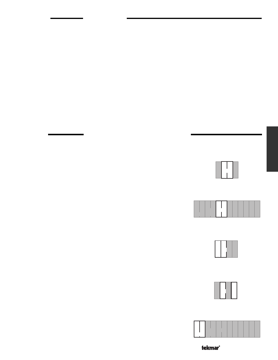
Powered Input Connections
120 V (ac) Power
Connect the 120 V (ac) power supply to terminals
Power N — L (2 and 3).
DHW Demand
If a DHW Demand is used, connect the wiring from the DHW Demand circuit to
terminals
DHW Dem — DHW Dem (22 and 23). When 120 V (ac) or 24 V (ac) is applied
to these terminals, the control recognizes a DHW Demand.
Output Connections
System Pump
Connect one wire from the system pump to the
Sys Pmp (1) terminal on the control. The
other wire on the system pump must be connected to the Neutral (2) side of the 120 V
(ac) power supply. The control closes a dry relay contact between
Sys Pmp — Power L
when operation of the system pump is required.
Variable Speed Injection Pump
The 370 can vary the speed of a permanent capacitor, impedence protected or
equivalent pump motor that has a locked rotor current of less than 2.4 A. Most small
wet rotor circulators are suitable as described in Essay E 021.
The variable speed
output must not be used on pumps which have a centrifugal switch. The 370 has an
internal overload protection fuse which is rated at 2.5 A 250 V (ac). This fuse is not field
replaceable. Contact your tekmar sales representative for details on the return and
repair procedures if this fuse is blown.
Connect one wire from the variable speed injection pump to the
Var. Pmp (4) terminal
on the control. The other wire on the variable speed injection pump must be connected
to the
Neutral (2) side of the 120 V (ac) power supply, or to L2 for a 240 V (ac) power
supply. The control varies the power to the pump in order to change its speed.
Boiler
Connect the 120 V (ac) or 24 V (ac) Boiler circuit to terminals
Boiler — Boiler (18 and
19). The 370 closes a dry relay contact between these terminals when boiler operation
is required.
2
26
28
3
1
25
24
Com
1-2
Com
3-4
27
4
29
18 19
Boiler
20 21
DHW
Pmp / Vlv
22 23
DHW
DemDem
3
1
2
N
L
Sys
Pmp
Po
wer
4
Var.
Pmp
4
3
1 2
N
L
Sys
Pmp
Var.
Pmp
wer
Po
3
1
2
N
L
Sys
Pmp
Po
wer
4
Var.
Pmp
2
26
28
3
20
22 23
21
1
25
24
Com
1-2
Com
3-4
27
4
29
18 19
Boiler
DHW
Pmp / Vlv
DHW
DemDem
Installation