Sequence of operation – tekmar 361 Mixing Control User Manual
Page 4
Copyright © D 361 -
03/09
4 of 20
Sequence of Operation
Section A
General Operation
Page 4-5
Section B
Mixing
Page 5-8
Section C
Boiler Operation
Page 8-9
Section A —General Operation
POWERING UP THE CONTROL
When the Mixing Control 361 is powered up, the control displays the control type number in the LCD for 2 seconds. Next, the software
version is displayed for 2 seconds. Finally, the control enters into the normal operating mode.
OPERATION
The 361 uses a variable speed injection pump to control the supply water temperature to a hydronic system. The supply water
temperature is based on either the current outdoor temperature, or a fixed setpoint.
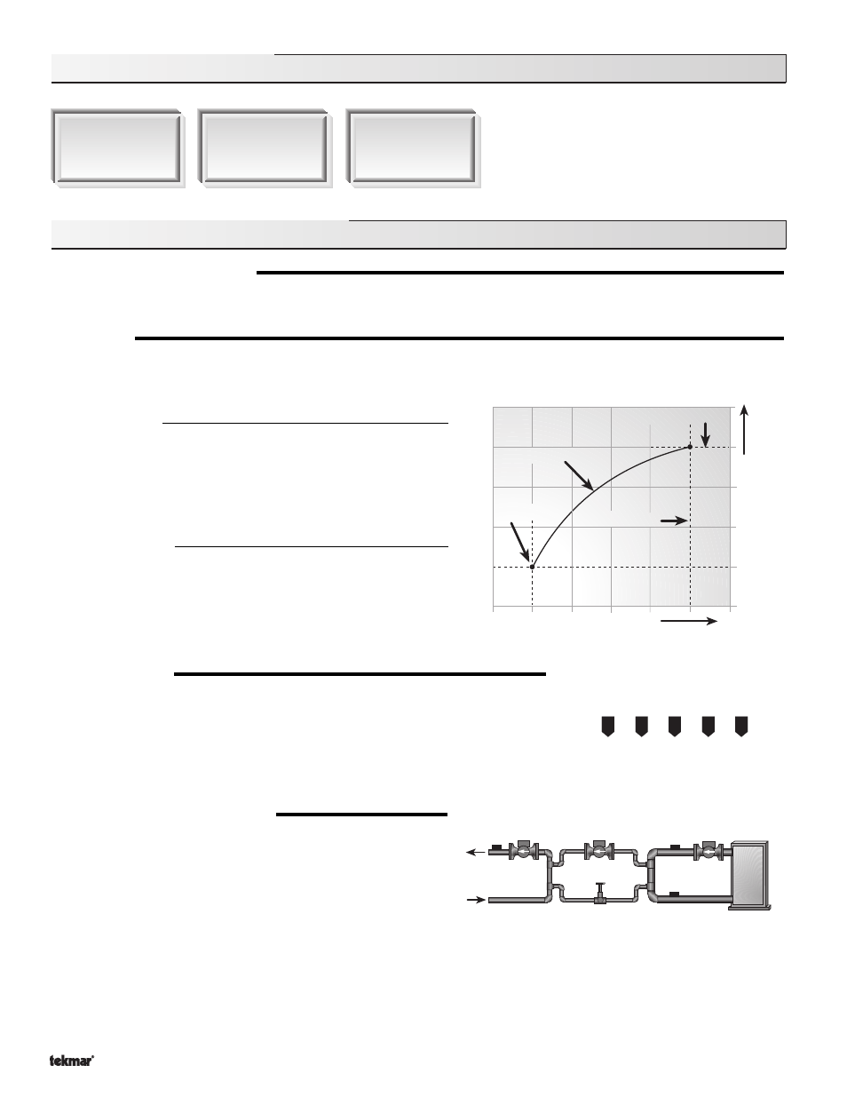
Outdoor Reset
When the outdoor design (OUTDR DSGN) setting is not set to OFF, the
361 calculates a mixing supply temperature based on the outdoor air
temperature. The 361 uses a
Characterized Heating Curve and
optionally indoor temperature feedback from an indoor sensor in this
calculation.
Setpoint Control
When the outdoor design (OUTDR DSGN) setting is set to OFF, the
361 supplies a fixed mixing supply temperature equal to the MIX
TARGET setting. An outdoor sensor is not required during this mode
of operation.
VARIABLE SPEED
A standard wet rotor circulator is connected to the 361 on the
Var Pmp and N terminals (7
and 8). The 361 increases or decreases the power output to the circulator when there is a
mixing demand. The circulator speed varies to maintain the correct mixed supply water
temperature at the mix sensor. For correct sizing and piping of the variable speed driven
circulator, refer to essay E 021. A visual indication of the current variable speed output is
displayed in the LCD in the form of a horizontal bar graph.
BOILER PROTECTION (BOIL MIN)
The 361 is capable of providing boiler protection from cold mixing system
return water temperatures. If the boiler sensor temperature is cooler than
the BOIL MIN setting while the boiler is firing, the 361 reduces the output
to the variable speed injection pump. This limits the amount of cool return
water to the boiler, and allows the boiler temperature to recover. This
feature can only be used if a boiler sensor is installed.
% Out
Current output of variable
speed injection pump
30
10
70
50
90
Mixing
sensor
Boiler return
sensor
Boiler supply
sensor
or
Outdoor Design
Increasing W
ater
T
emperature
Design Supply
Decreasing Outdoor Temperature
Terminal Unit
Indoor Design