tekmar 313 tN2 Wiring Center Installation User Manual
Page 6
© 2011
D 313 - 05/11
6 of 12
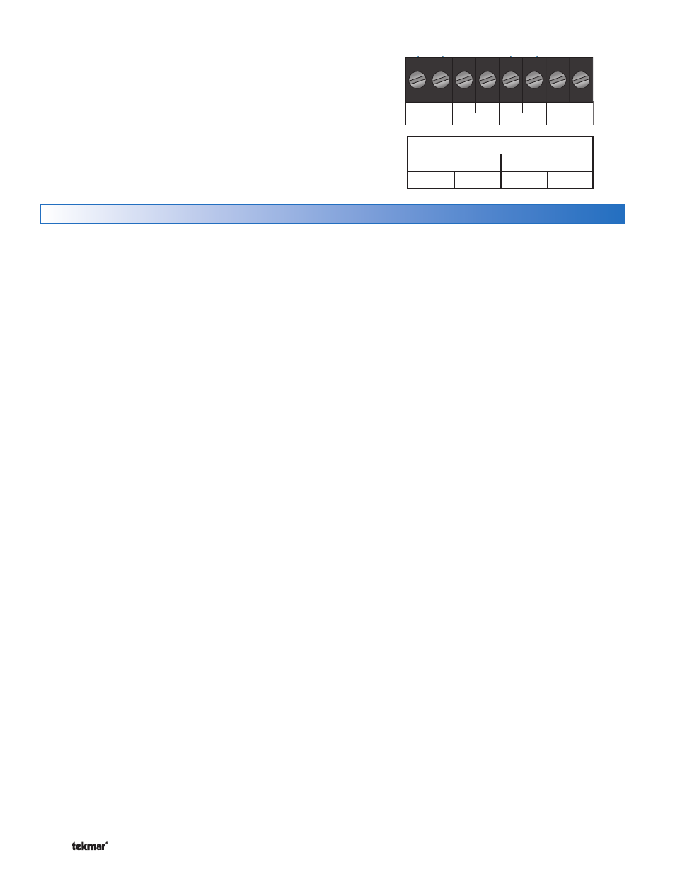
A two stage thermostat is automatically detected when
connected to Zone 1 or Zone 3. If there is no tN2 thermostat
connected to Zone 2 or Zone 4, these outputs will automatically
operate the heating equipment for second stage heat.
Testing the Control Wiring
Testing the Power
-----------------------------
-----------------------------
If the control Power light does not turn on, check the Input
Power wiring terminals using an electrical multimeter. The
voltage should measure between 21.6 to 26.4 V (ac). If the
voltage is below this range, measure the line voltage side
of the transformer. The voltage should measure between
103.5 to 126.5 V (ac).
Testing the Thermostats ----------------------
----------------------
If the thermostat display turns on, this indicates that the
thermostat is operating correctly and there are no electrical
issues. In the event that the display is off, or the display is
cycling on and off, follow this procedure.
1. Remove the tN2 wires from the thermostat.
2. Use an electrical meter to measure DC voltage between
the tN2 terminals.
If the DC voltage is 0 V (dc) for 20 seconds, then there is
an open or short circuit in the tN2 wires. If the DC voltage
is 0 V (dc) for 10 seconds and then is 23 to 24 V (dc) for 5
seconds, this indicates the wiring is correct.
3. Connect the thermostat to the tN2 wires from a zone
on a House Control, Wiring Center, or Zone Manager.
4. If the thermostat display is off, or is cycling on and off,
move the thermostat to the next available zone on the
House Control, Wiring Center, or Zone Manager.
If the thermostat display remains permanently on, there
may be a fault with the previously tried zone on the House
Control, Wiring Center, or Zone Manager.
If the thermostat display continues to be off, or is cycling
on and off, there may be a fault on the thermostat.
If a fault is suspected, contact your tekmar sales representative
for assistance.
Testing the Zone Output ----------------------
----------------------
1. Use an electrical test meter to measure the (ac) voltage
between the C and the Vlv terminals for each zone valve
output.
Lower the thermostat temperature setting. When the
zone LED is off, the reading should be 0 V (ac) and the
valve should be closed.
Raise the thermostat temperature setting. When the
zone LED is on, the reading should be 24 V (ac) + / –
10% and the valve should be open.
•
•
Note: If power to the zone valve is present but the zone
valve does not operate properly, refer to any troubleshooting
information supplied by the zone valve manufacturer.
Testing tekmarNet
®
4 Expansion --------------
--------------
To test the tN4 Network, check the wires for continuity
and shorts.
1. Disconnect the two tN4 expansion wires (tN4 and C) at
one end and twist them together.
2. Go to the other end of the wires and disconnect
them.
3. Using an electrical test meter, check for continuity.
Resistance should read 0 ohms, or continuity should
produce a tone. If not, this indicates that there are
damaged wires connecting the tN4 control to the 313.
Repair or replace the wires as necessary.
4. Go back to the original end of the wires and, using a
wire nut, cap each expansion wire individually so that
these ends cannot touch another conductor.
5. Go to the other end of the wires and again, test for
shorts. Resistance should be infinite, or O.L. and there
should be no tone. If tone exists or less than 50 000
ohms is found, then the wires are not insulated from
one another. This is generating a short on the wires
connecting the tN4 control to the 313.
6. Replace the damaged wires, test, and reconnect them
to their proper terminals.
Testing The End Switch / Zone Group Pump --
--
If the tN4 expansion terminals are not used to connect the
313 to the system, the end switch may be used.
1. Remove the wires from the end switch terminals.
2. Use an electrical test meter to measure continuity across
the XX end switch terminals on the 313.
When the end switch LED is off, no continuity should
be present (no tone).
When the end switch LED is on, continuity should be
present (tone).
3. Use an electrical test meter to measure voltage across
the zone group pump hot switch leg and neutral.
When the end switch LED is off, the voltage should be
0 V (ac).
When the end switch LED is on, the voltage should be
between 103.5 to 126.5 V (ac).
•
•
•
•
Two-Stage tekmarNet
®
2 Thermostat Wiring -----------------------------------------------------------
-----------------------------------------------------------
Zone 1
Zone 2
Zone 3
Zone 4
tN2 tN2 tN2 tN2 tN2 tN2 tN2 tN2
Two-Stage Terminal Designation
Zone 1
Zone 3
Stage 1
Stage 2
Stage 1 Stage 2