Sequence of operation, User interface, Power zone 1 zone 2 zone 3 zone 4 end switch – tekmar 313 tN2 Wiring Center Installation User Manual
Page 10
© 2011
D 313 - 05/11
10 of 12
Sequence of Operation
tekmarNet
®
System
Section A
tekmarNet
®
is a family of products that use communication
to operate the HVAC system in a comfortable and efficient
manner. The Wiring Center is a zoning component in
a tekmarNet
®
system and requires tekmarNet
®
2 (tN2)
Thermostats to be directly connected to it.
The tekmarNet
®
4 (tN4) Expansion terminals can link the
Wiring Center with other tekmarNet
®
components:
House Controls 400, 401, 402, 403 - Provides boiler and
DHW control
•
Reset Modules 420, 421, 422, 423
Boiler Controls 274, 275
Wiring Centers 313, 314, 315, 316 - Add additional zones
tN4 Thermostats - Add thermostats
tN4 Timer 033 - Adds 4 programmable schedules
tN4 User Switch 479 - Provides a system override for
vacations and holidays
tN4 Setpoint Control 161, 162 - Control hot tubs, pools
and more
•
•
•
•
•
•
•
ZONE 1
The zone 1 thermostat is calling for heat
and the 24 V (ac) output is energized.
ZONE 2
The zone 2 thermostat is calling for heat
and the 24 V (ac) output is energized.
ZONE 3
The zone 3 thermostat is calling for heat
and the 24 V (ac) output is energized.
ZONE 4
The zone 4 thermostat is calling for heat
and the 24 V (ac) output is energized.
POWER
24 V (ac) is being applied to the Wiring
Center to provide it with power.
END SWITCH
At least one of the zone thermostats are
calling for heat and the end switch relay
output is closed.
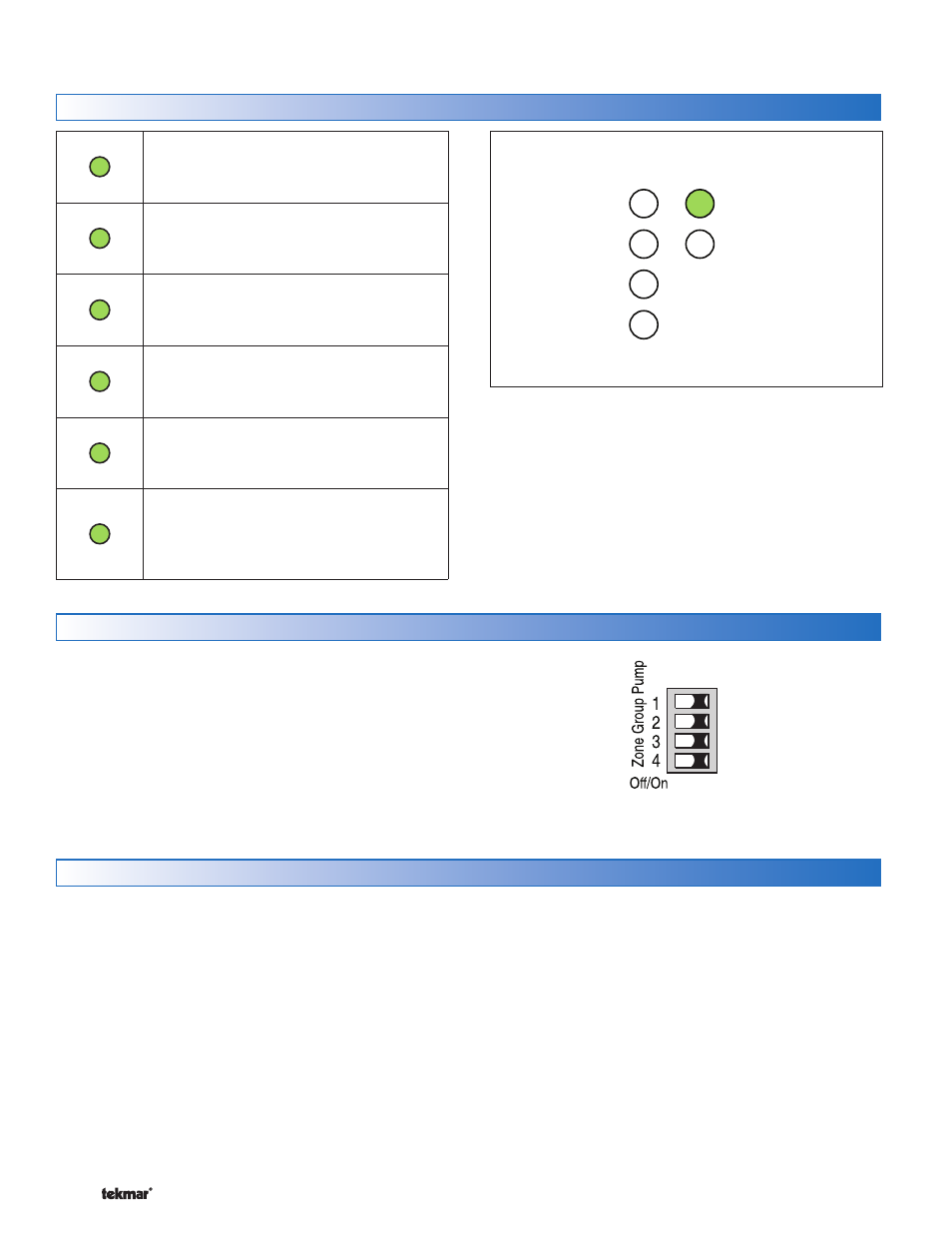
LEDs
User Interface
Power
Zone 1
Zone 2
Zone 3
Zone 4
End Switch
Wiring Center 313
Zone LED Flashing ----------------------------
----------------------------
The zone has an open or short circuit and communication
to the thermostat on the zone has been interrupted. Check
the wiring between the thermostat and the Wiring Center
for open or short circuits. If the thermostat was intentionally
removed, power the Wiring Center off for 10 seconds.
DIP Switches
Each zone has a corresponding zone group pump DIP
switch. Set the switch to On to operate the zone group pump
output whenever that zone calls for heat. When the DIP
switch is set to off, the zone group pump will not operate
when that zone calls for heat.