tekmar 313 tN2 Wiring Center Installation User Manual
Page 5
5 of 12
© 2011
D 313 - 05/11
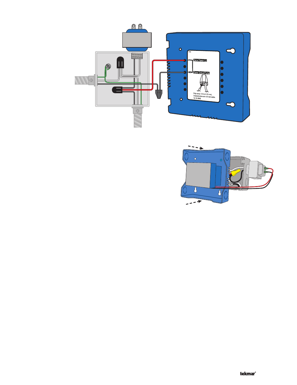
Power Source
(L, N, Ground)
Zone Group
Pump
(L, N, Ground)
(red)
Figure 1 - Connect
Line Voltage Wires
External Power Supply
It is strongly recommended that a transformer with an in-line
fuse be used in order to protect the transformer from high
currents. The tekmar Transformer 009 includes a fuse.
Connect the 24 V (ac) leads from the transformer to the C
and R terminals marked “Input Power” on the 313.
tekmarNet
®
2 Thermostats
The 313 is designed to operate with tekmarNet
®
2 Thermostats.
They provide the heating and cooling control for each zone,
and communicate with any other tekmarNet
®
device on
the system.
Connect the tN2 terminals from each thermostat to the
corresponding tN2 terminals for each zone on the 313.
Zone Valves
Wire the zone valves to the C and Vlv terminals on the 313.
End switches on zone valves are not required when
using the 313.
•
•
•
•
Low Voltage Wiring -----------------------------------------------------------------------------------
-----------------------------------------------------------------------------------
The enclosure may be mounted directly to a wall or to
an electrical junction box.
Ensure that the high voltage wires are neatly tucked
inside the electrical junction box.
Using 2 of the 4 holes in the back of the enclosure, securely
fasten it to the electrical junction box with 2 #10 screws as
shown in Figure 2.
•
•
•
Install The Enclosure ---------------------------------------------------------------------------------
---------------------------------------------------------------------------------
Figure 2
tN4 Expansion Terminals
The 313 uses the Expansion tN4 and C terminals to communicate
with additional Wiring Centers, House Controls, and other
tekmarNet
®
devices.
Connect the tN4 and C Expansion terminals on the 313
to the corresponding tN4 and C Expansion terminals of
the additional external device.
Wiring the End Switch
The 313 can operate a single on-off boiler or provide a
demand to a tekmar control.
Connect the X X End Switch terminals on the 313 to the
T-T (or R-W) terminals on the boiler.
If required, use the X X End Switch terminals to switch
24 V (ac) to power a demand on a tekmar outdoor reset
control.
Wiring the Outdoor Sensor
The 313 has an optional outdoor sensor input.
Wire the outdoor sensor to the Out and Com terminals
on the 313.
The outdoor temperature will be displayed on all ther-
mostats connected to the 313.
•
•
•
•
•