Step five — electrical connections to the control, Test the outputs, Powered input connections – tekmar 257 DHW Control User Manual
Page 7: Output connections, Sensors, Test the power supply
7
of
12
©
2009 D
257
-
03/09
Test the Outputs
Heat 1 and Heat 2
Make sure power is off to the boiler circuits and connect
the TT contacts on the boilers to the Heat 1 and Heat 2
contacts on the control. Install jumpers at the Heat 1 and
Heat 2 terminals to externally close the switch. When
the boiler circuits are powered up, the boilers should fire.
If the boilers do not turn on, refer to any installation or
troubleshooting information supplied with the boilers (the
boilers may have a flow switch that prevents firing until the
boiler pumps are running). If the boilers operate properly,
disconnect the power and remove the jumpers.
3
4
Heat 1
Jumper wire
between
terminals
T-T contacts
on boiler
DHW
Control 257
Step Five — Electrical Connections to the Control
The installer should test to confirm that no voltage is present
at any of the wires.
Powered Input Connections
24 V (ac) Power
Connect the 24 V (ac) power supply to the Power C and
Power R terminals (1 and 2). This connection provides
power to the microprocessor and display of the control.
L
N
R
C
1
2
Power
C
R
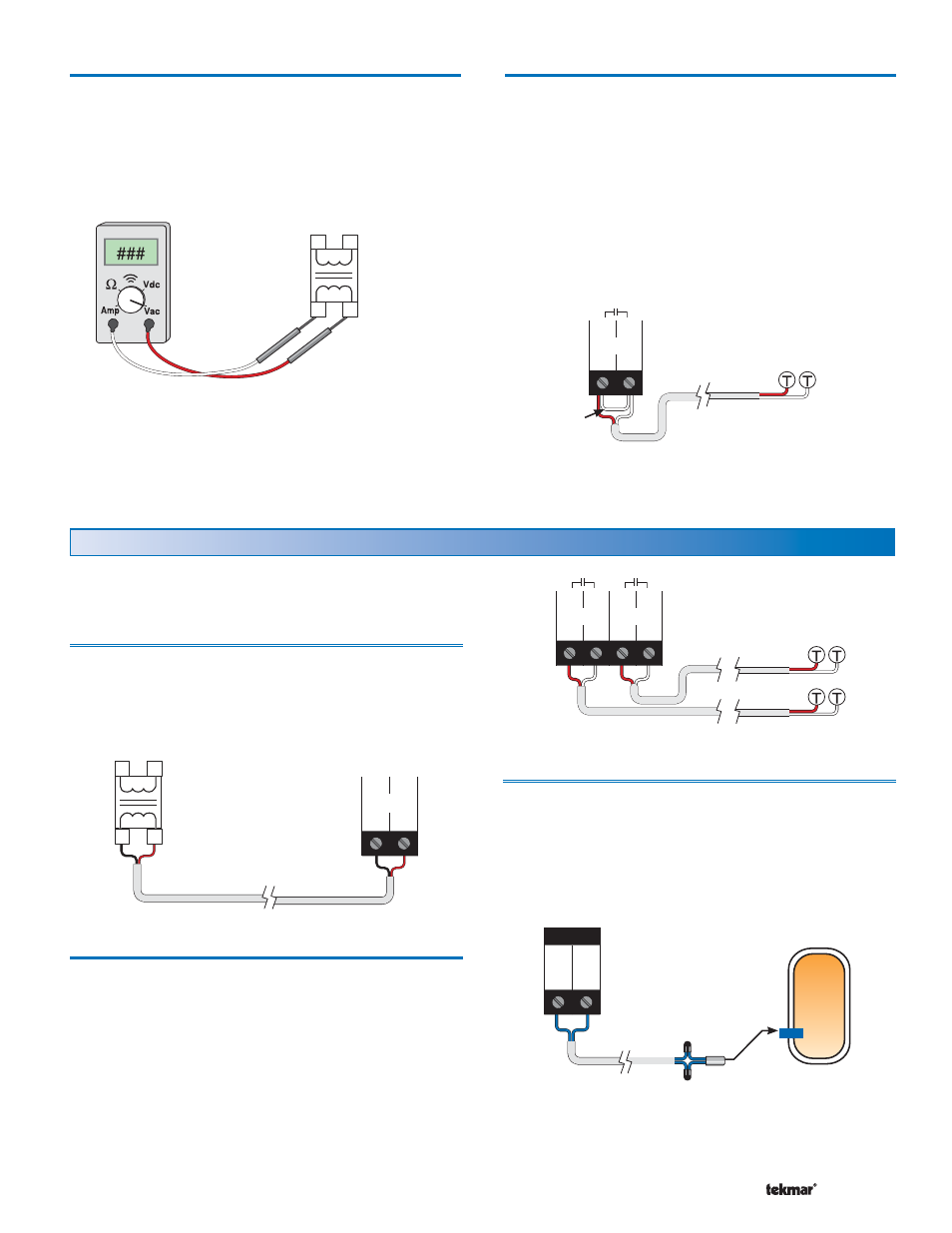
Output Connections
Heat 1 and Heat 2 Contacts
The Heat 1 and Heat 2 contacts are an isolated output in the
257. There is no power available on these terminals from the
control. These terminals are to be used as a switch to either
make or break the boiler TT circuit. When the 257 requires
boiler 1 to run, it closes the contact between terminals 3
and 4, and when the 257 requires boiler 2 to run, it closes
the contact between terminals 5 and 6.
3
4
5
6
Heat 1
Heat 2
Sensors
Do not apply power to these terminals as this will
damage the control.
DHW Sensor
Connect the two wires from the DHW Sensor 082 to the
Com and DHW terminals (7 and 8). The DHW Sensor is
used by the 257 to measure the DHW tank temperature.
Locate the sensor in a well in the tank. The 082 sensor is
3/8” OD and will insert into a standard 1/2” well.
Test the Power Supply
Make sure exposed wires and bare terminals are not in
contact with other wires or grounded surfaces.
If a 24 V (ac) transformer is used, make sure the voltmeter
is set to AC. Turn on the power and measure the voltage
across the 24 V (ac) power supply. The reading should be
between 22 and 26 V (ac).
Class 2
Transformer
L
N
R
C
No Power
7
8
Com DHW
Sen Sen
DHW
Tank