Installation – tekmar 257 DHW Control User Manual
Page 6
©
2009 D
257
-
03/09
6
of
12
Step Three — Rough-in Wiring
The wiring terminates in the two wiring chambers on the
control. Determine whether the low voltage wiring enters
the wiring chamber through the back or the bottom of the
control. The wiring is roughed-in prior to installation of the
control (see Brochure D 001). Standard 18 AWG solid wire
is recommended for all low voltage wiring, and multi-strand
16 AWG wire is recommended for 120 V (ac) wiring.
Power must not be applied to any of the wires during
the rough-in wiring stage.
Install the DHW Sensor 082 according to the instructions
in the Data Brochure D 070, and run the wiring back to
the control.
Run wires from the 24 V (ac) power to the control. Use a
clean power source to ensure proper operation.
•
•
Step Four — Testing the Wiring
The following tests are to be performed using standard
testing practices and procedures, and should only be
carried out by properly trained and experienced persons.
A good quality electrical test meter, capable of reading from
at least 0 - 300 V (ac) and at least 0 - 2,000,000 Ohms, is
essential to properly test the wiring and sensors.
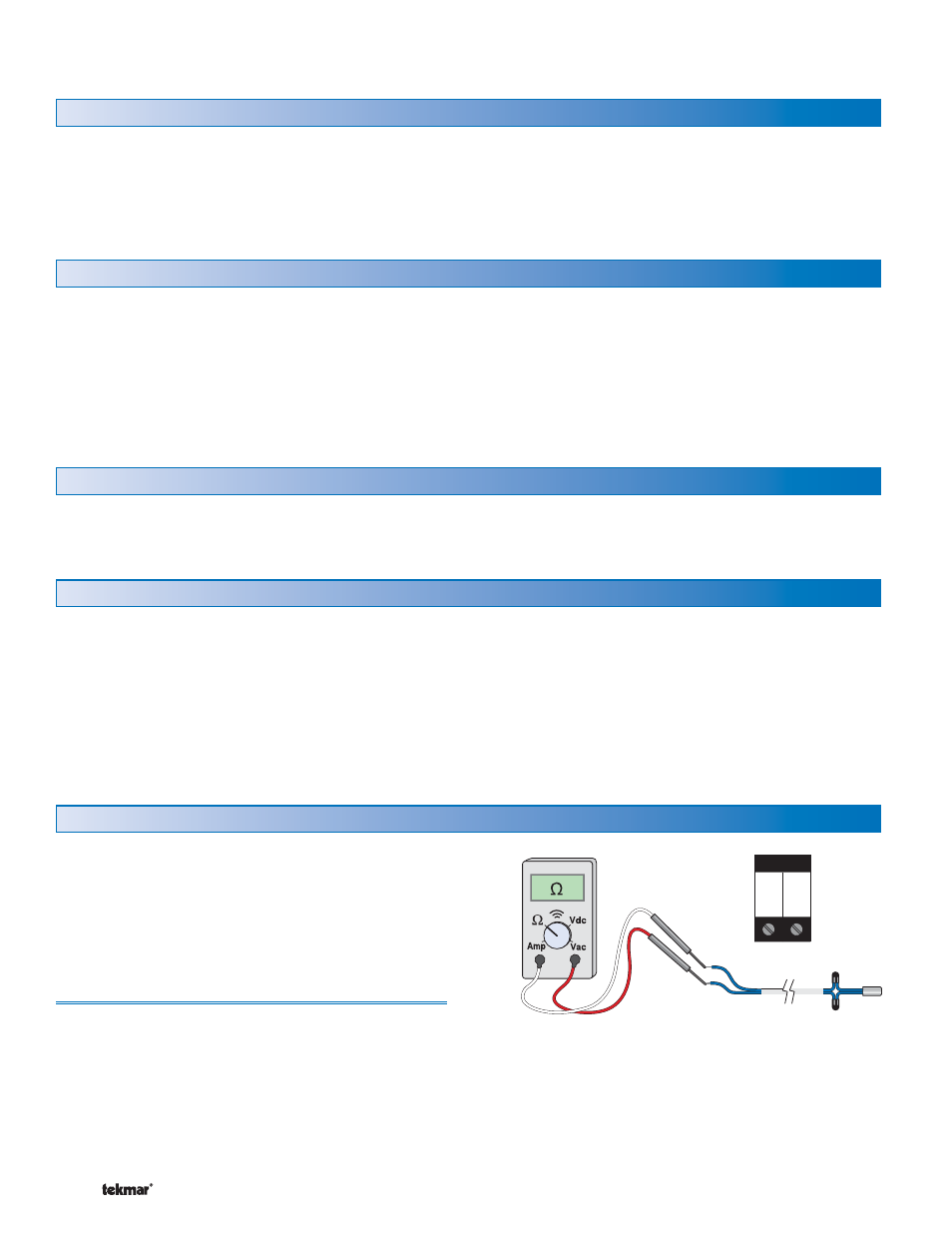
Test the Sensors
In order to test the sensors, the actual temperature at
each sensor location must be measured. A good quality
digital thermometer with a surface temperature probe is
recommended for ease of use and accuracy. Where a
digital thermometer is not available, a spare sensor can be
strapped alongside the one to be tested, and the readings
compared. Test the sensors according to the instructions
in the Data Brochure D 070.
Improper installation and operation of this control could
result in damage to the equipment and possibly even
personal injury. It is your responsibility to ensure that this
control is safely installed according to all applicable codes
and standards. This electronic control is not intended
for use as a primary limit control. Other controls that are
intended and certified as safety limits must be placed into
the control circuit.
Caution
Installation
Step One — Getting Ready
Check the contents of this package. If any of the contents
listed are missing or damaged, please contact your
wholesaler or tekmar sales representative for assistance.
Type 257 includes: One DHW Control 257, One Universal
Sensor 082 Data Brochures D 257, D 070, D 001, Application
Brochure A 257.
Note: Carefully read the details of the Sequence of
Operation to ensure that you have chosen the proper
control for your application.
The control is mounted in accordance with the instructions in the Data Brochure D 001.
Step Two — Mounting
No Power
7
8
Com DHW
Sen Sen