Burnham RSA User Manual
Page 31
3
Then, press the UP and/or DOWN buttons to
move the set point to the desired value. After 60
seconds without any button inputs, the control will
automatically return to the RUN mode.
Note that L7224 Aquastat Controller will display all
four (4) above-listed adjustment features, but L7248
Aquastat Controller will not display Low Limit and
Low Limit Differential adjustment features.
6.
DISPLAY READOUT
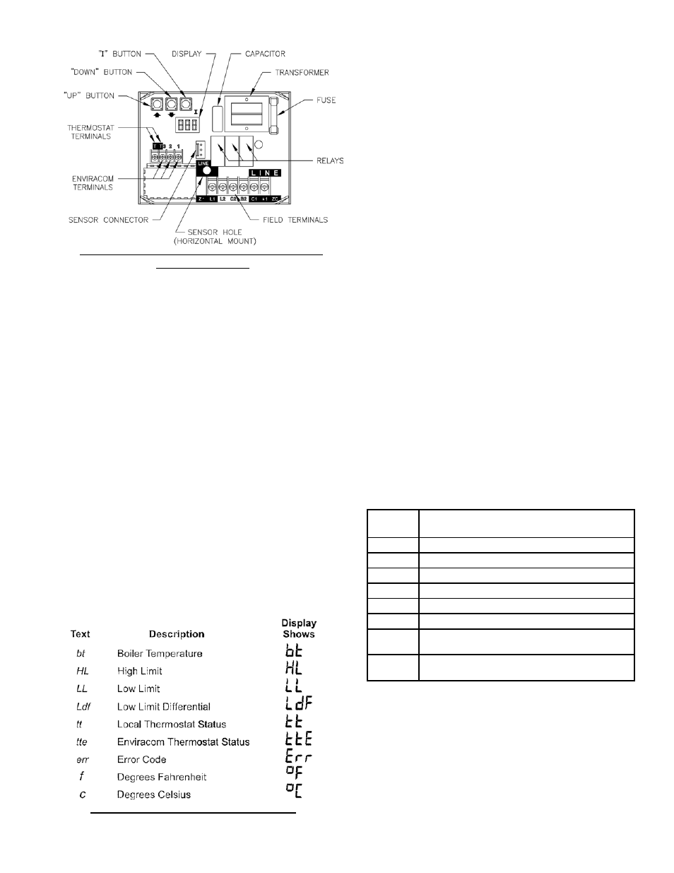
In the RUN mode, the Aquastat will flash "bt"
(boiler temp) followed by the temperature (i.e.,
220), followed by °F or °C.
To read boiler settings, press the I key to read the
parameter of interest. For example, press I High
Limit (HL) is displayed, followed by a three-digit
number, i.e., 220, followed by °F or °C. Pressing
the I button again (on L7224 models) will display
the Low Limit (LL) followed by a three-digit
number and the corresponding degree designator.
See Display Readout, Figure 23.
After approximately 60 seconds without any key
presses, the display will enter a dim display mode.
To return to the bright display mode, simply press
any key.
7. OPERATION
The L7224 model can be in any of four operational
states - Normal, High Limit, Low Limit and Error.
The controller moves back and forth from High
Limit to Normal to Low Limit state as part of
normal operation.
The L7248 model is restricted to three operational
states - Normal, High Limit and Error. The
controller moves back and forth from High Limit to
Normal state as part of normal operation.
For both models, the controller will enter the Error
state when there is an abnormal condition. The
operating states are:
a. Normal: Boiler temperature went below the
High Limit setting (minus the Differential) and
has not exceeded the High Limit setting; or the
boiler temperature went above the Low Limit
setting and has not gone below the Low Limit
setting (minus the Differential).
b. High Limit: Boiler temperature went above the
High Limit setting and has not dropped below
the High Limit setting (minus the Differential).
c. Low Limit: Boiler temperature went below
the Low Limit setting (minus the Low Limit
Differential) and has not gone above the Low
Limit setting.
d. Error: The controller has detected an error
condition (e.g., open sensor) and has shut down
the burner output. The ZC output is energized.
The controller continues to monitor the system
and automatically restarts if the error condition
clears. Refer to Table 4.
Figure 22: L7248/L7224 Circuit Board Layout -
Horizontal Mount
Figure 23: Display Readout Definitions
Table 4: LED Error Codes
Error
Code
Cause / Action
Err1
Sensor fault; check sensor.
Err2
ECOM fault; check EnviraCOM™ wiring.
Err3
Hardware fault; replace control.
Err4
B1 fault; check B1 wiring/voltage.
Err5
Low Line; check L1-L2, 110 Vac.
Err6
Fuse; check ECOM wires, replace fuse.
Err7
EEPROM, HL, LL, Hdf, Ldf; reset to default values.
Restore desired settings.
Err8
Repeated B1 fault (voltage present at B1 when out-
put is turned off); check B1 wiring/voltage.
The operating sequence for the L7224/L7248 is
shown in Table 5. See Table 6 for Trouble Shooting
Guide.
8. HIGH LIMIT CONTROLLER
The High Limit opens and turns off the burner
when the water temperature reaches the setpoint.
The High Limit automatically resets after the water
temperature drops past the setpoint and through the