E-flite Power 32 Brushless Outrunner Motor, 770Kv User Manual
Page 3
1.
This brushless motor requires the use of a sensorless brushless speed control. Failure to use the correct speed control may result in damage to the
motor and/or speed control. Please be sure the timing and PWM switching frequency is set properly on your controller.
2.
When mounting the motor, be sure the correct length of screws are used so damage to the inside of the motor will not occur. We suggest you use
the mounting hardware included with your motor. The use of long screws will damage the motor.
3.
You may connect the three motor wires directly to the controller with solder or use connectors such as gold plated brushless bullet connectors
(EFLA241), which will also need to be soldered properly to your wires. The three motor wires can be connected in any order to the three output
wires or output port on a sensorless brushless speed control. Be sure to use heat shrink tubing to properly insulate the wires so the wires will not
short. Shorting may damage the motor and speed control.
4.
If you add connectors and you no longer wish to use them, never cut the motor wires. Remove them by properly desoldering them. Shortening the
motor wires is considered an improper modification of the motor and may cause the motor to fail.
5.
When you connect the motor to the esc, check the rotation direction of the motor. If you find the rotation is reversed, switching any two motor
wires will reverse the direction so the motor rotates properly.
6.
Proper cooling of the motor is very important during operation. New technology has brought much higher capacity batteries with higher discharge
rates, which can cause extreme motor temperatures during operation. It is the responsibility of the user to monitor the temperature and prevent
overheating. Overheating of the motor is not covered under any warranty.
7.
You can install the propeller on the motor shaft after you have confirmed proper rotation direction. Also consult the instruction included with your
sensorless electronic speed control for proper adjustments and timing.
8.
Once the battery is connected to the motor, please use extreme caution. Stay clear of the rotating propeller since spinning propellers are very
dangerous as the motors produce high amounts of torque.
9.
Never disassemble the motor. This will void any warranty.
Reversing the Shaft:
This Outrunner motor has a shaft, which exits through the rotating part of the motor. If you want to reverse the shaft to exit through the fixed part of the motor,
follow these instructions carefully for changing the shaft installation. Be sure to use the correct sized wrench or you may strip the set screw. NOTE: The user
assumes all liability for damage that may occur.
1.
Loosen the set screw on the shaft collar and remove the collar from its location against the bearing.
2.
Remove the small black donut washer that rests against the bearing.
3.
Loosen the two set screws in the rotating part of the motor.
4.
Slide the shaft through the motor. It may be necessary to use a small hammer to lightly tap the shaft. It is very important that you do not bend the
shaft in this process so use extreme caution to assure this does not happen.
5.
Re-install the donut washer against the bearing. Do not skip this step.
6.
Re-install the shaft collar back against the washer and bearing.
7.
Retighten all setscrews making sure you line up with the flat spot on the shaft.
Replacement shafts are available separately. Order EFLM40321 for a Power 32 BL Outrunner shaft.
Safety Precautions:
This is a sophisticated hobby product and not a toy. It must be operated with caution and common sense and requires some basic mechanical ability. Failure
to operate this product in a safe and responsible manner could result in injury or damage to the product or other property. This product is not intended for
use by children without direct adult supervision. The Outrunner motor case is a rotating part so use extreme caution. Please read the warning
information included with your propellers for safety information related to the operation of motors with propellers. Failure to comply with these warnings and/or
improper use of propellers may result in serious injury.
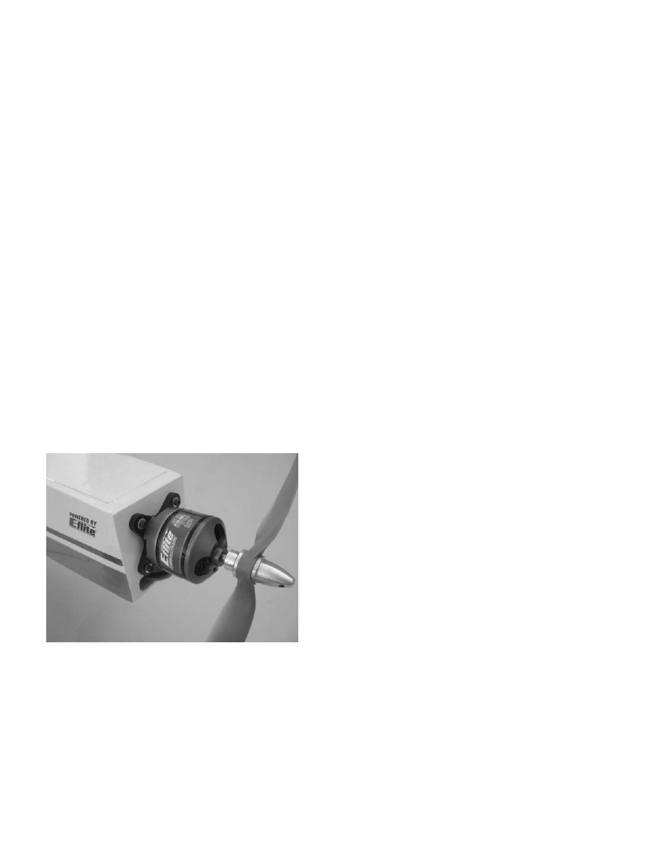
Installation:
NOTE: Photo shows typical installation of motor and x-mount directly to the outside of the firewall. There are other options available including mounting the
motor inside the fuselage (requires reversing the shaft direction) or extending the motor further forward using aftermarket mount extensions when using cowls.
1.
You can first trial fit the aluminum x-mount against the front of the firewall and use a Sharpie® to mark the locations of four holes and drill
appropriate size hole to fit the blind nuts provided. Always be sure to maintain the proper thrust line and account for adequate prop/spinner
clearance.
2.
Attach aluminum x-mount to the outrunner motor using the four flat head (countersunk) screws provided with the motor.
3.
Install four blind nuts on the inside of the firewall.
4.
Attached the aluminum x-mount and motor to the outside of the firewall using the four socket head cap screws and washers.
Limited Warranty Period
Horizon Hobby, Inc. guarantees this product to be free from defects in both material and workmanship for a period of 1 year from the date of purchase.
Limited Warranty
(a) This warranty is limited to the original Purchaser ("Purchaser") and is not transferable. REPAIR OR REPLACEMENT AS PROVIDED UNDER THIS WARRANTY IS THE
EXCLUSIVE REMEDY OF THE PURCHASER. This warranty covers only those Products purchased from an authorized Horizon dealer. Third party transactions are not covered by
this warranty. Proof of purchase is required for warranty claims. Further, Horizon reserves the right to change or modify this warranty without notice and disclaims all other
warranties, express or implied.