E-flite 11.0-Gram G110 Micro Heading Lock Gyro User Manual
G110 micro heading lock gyro instruction manual
G110 Micro Heading Lock
Gyro Instruction Manual
Introduction
The G110 Micro Heading Lock Gyro’s small size
(25 x 25 x 16mm) and low weight (11.0 grams, including leads
and connectors) make it an ideal choice for a wide variety of
micro and mini class electric helicopter models. With features
like analog and digital servo support, optional dual remote
gain adjustment and heading lock or standard rate mode
selection capabilities, it offers locked-in tail performance
and adjustability perfect for the sport and 3D pilot alike.
Gyro Installation
When installing the G110, it is typically best to first refer
to your helicopter’s instruction manual for suggestions of
the location in which it should be mounted on the model.
If no suggestions are available, choose a solid location
free from vibration, in line with the yaw axis of the model.
Also, be sure to keep the gyro away from heat-generating
sources (like the motor and ESC) and other electronics.
When mounting the G110, be sure the side of the gyro
with the label is mounted vertically on the model (parallel
to the main shaft). The sides of the gyro without the leads
and switches are the top and bottom respectively. Also,
be sure to position the gyro so you can easily access the
gain setting adjustment pot (if not using the remote gain
adjustment option), reversing and servo mode switches.
Once you have found a suitable location, use a small amount
of isopropyl alcohol to clean the mounting area and gyro
where the foam mounting tape will be attached. Then,
use the included foam mounting tape to mount the gyro
securely on the model. It is important to use foam mounting
tape only, as it helps to prevent vibration from adversely
affecting the performance and operating life of the gyro.
Gyro Connection(s) to Receiver
Single Mode Connection (Heading Lock Mode Only)
If you will
not
be utilizing the dual remote gain adjustment
and mode selection option to control gain values and mode
type from an auxiliary channel on the transmitter, it will only
be necessary to connect the rudder channel lead of the gyro
(the connector with three wire leads) to the rudder channel
on the receiver. You will not need to connect the auxiliary
channel lead of the gyro (the connector with one wire lead)
to the receiver, however, be certain to secure it so it cannot
come into contact with any moving parts on the helicopter.
With just the rudder channel lead of the gyro connected
to the receiver, the gyro will operate in heading lock
mode only. The gain value will then be adjusted using
the gain setting adjustment pot located on the gyro.
Dual Mode Connections
(Heading Lock and Standard Rate Mode)
If you have chosen to utilize the dual remote gain adjustment
and mode selection option to control gain values and mode
type from an auxiliary channel on the transmitter, it will be
necessary to connect the rudder channel lead of the gyro (the
connector with three wire leads) to the rudder channel on
the receiver, and the auxiliary channel lead of the gyro (the
connector with one wire lead) to the channel on the receiver
that will be used for controlling the gyro from the transmitter.
For most radio systems, it will be best to connect the auxiliary
channel lead of the gyro to channel 5 (also known as the gear
channel) on the receiver, ensuring the yellow wire lead is oriented
properly and plugged into the “signal” pin on the receiver.
With both the rudder channel and auxiliary channel leads of
the gyro connected to the receiver, the gyro can be operated
in either the heading lock or standard rate mode. Mode
selection and gyro gain settings will then be adjusted using
the chosen auxiliary channel on the transmitter, and the gain
setting adjustment pot located on the gyro will be disabled.
Tail Servo Selection
Selection of a suitable tail servo is critical for obtaining
maximum performance from the gyro. A servo with quick
transit times (.15 sec/60° or faster) is preferred, and
will allow the G110 to perform to its full potential.
We suggest using the following servos in
their recommended applications:
• E-flite
®
S60 Super Sub-Micro Servo (EFLRS60)
– For sub-micro and micro helicopters
• E-flite S75 Sub-Micro Servo (EFLRS75)
– For micro and mini helicopters
• E-flite DS75 Digital Sub-Micro Servo (EFLRDS75)
– For micro and mini helicopters
• JR 3500G Mini Digital Heli Gyro Servo (JRPS3500G)
– For mini helicopters
• Spektrum
™
DSP60 Digital Programmable Super Sub-Micro
Servo (SPMDSP60)
– For sub-micro and micro helicopters
• Spektrum
DSP75 Digital Programmable Sub-Micro Servo
(SPMDSP75)
– For micro and mini helicopters
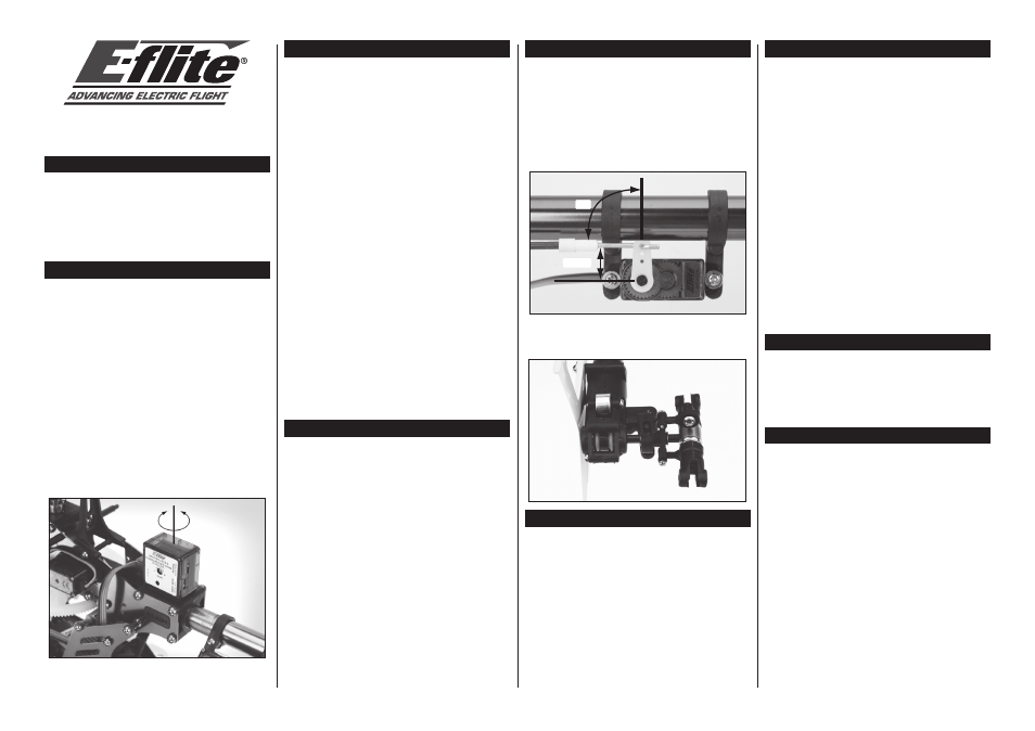
Servo Arm and Pushrod Setup
After installing your chosen servo on the model, it will be best
to center the servo electronically using an open channel before
installing the servo arm and connecting the servo to the G110.
Once you have centered the servo electronically, choose a servo
arm that allows the tail rotor pushrod linkage or linkage ball to
be positioned approximately 8–11mm (typical for T-REX 450
and similar models) from the center of the servo’s output gear/
shaft. Then, install the servo arm on the servo, ensuring it is
perpendicular to the tail rotor pushrod linkage when in the
centered/neutral position. Also, be sure to remove any unused
portions of the servo arm to prevent any binding or obstruction.
8-11mm
90º
After installing the tail rotor pushrod linkage on the tail servo
arm, and ensuring the tail servo is still centered electronically,
adjust the length of the pushrod so the tail pitch slider is centered
on the tail rotor shaft, between the tail case and tail hub.
Servo Connection to Gyro
Once the tail servo, servo arm and linkage have been installed
on the model, it will be necessary to connect the servo to
the G110. Connect the servo lead to the servo connection
on the gyro (the three pins exiting the gyro case), ensuring
proper orientation and polarity direction of the wire leads
by following the markings on the label of the gyro:
S
= Signal wire lead connection location
+
= Positive wire lead connection location
–
= Negative wire lead connection location
Servo Mode Setting
Standard (STD) Servo Mode
If you are using an analog servo (like the E-flite S75), be
sure the servo mode switch located on the side of the gyro
is set to the standard (STD) position for the best possible
performance. If it is set to the digital servo (DS) position,
the analog servo may not operate correctly and/or will be
damaged due to the high frame rate output of the gyro
when it is in the digital servo mode.
Do not use analog
servos with the gyro set for digital servo mode.
Digital (DS) Servo Mode
If you are using a digital servo (like the JR 3500G or Spektrum
DSP75), be sure the servo mode switch located on the side of
the gyro is set to the digital servo (DS) position for the best
possible performance. In the digital servo mode, the gyro
sends inputs to the servo at a much higher rate than when in
the standard servo mode for added performance and holding
power. However, you must be sure to use a digital servo that
is capable of handling an input pulse rate of 275Hz or higher
(like JR and similar digital servos), or the servo will not operate
correctly and/or will be damaged due to the high frame rate
output of the gyro when it is in the digital servo mode.
Do not
use digital servos that cannot handle an input pulse
rate of at least 275Hz, or analog servos, with the
gyro set for digital servo mode. Always consult the
manufacturer of your chosen digital servo to confirm
whether it can handle an input pulse rate of 275Hz.
Initial Transmitter Settings
After completing installation and connection of the G110
and tail servo on the model, please proceed with confirming
the following initial settings in your transmitter:
• Set the rudder channel trim and
sub-trim (if available) to neutral.
• Disable and inhibit any forms of Revolution (Revo) Mixing.
Initializing the Gyro
Once you have confirmed the initial settings in the
transmitter, it will be necessary to power up and
initialize the gyro before proceeding with some of
the following setup and adjustment steps:
• Power the transmitter on first.
• Then, power the receiver and gyro on.
• After powering on the receiver and gyro, make
sure you do not move or sway the model and
allow it to remain motionless until the red LED on
the gyro illuminates solidly, indicating the gyro
has initialized properly and is ready for use.
Note: It is extremely important you do not move or
sway the model after powering on the gyro and before
it initializes. The gyro must be allowed adequate time
to record the neutral position in order to initialize
for proper operation. If you accidentally move the
model after powering the gyro on, and before it has
initialized, power the model off and repeat the process
to power the model on and initialize the gyro properly.